Antennae
80m vertical testing
30/12/17 17:55
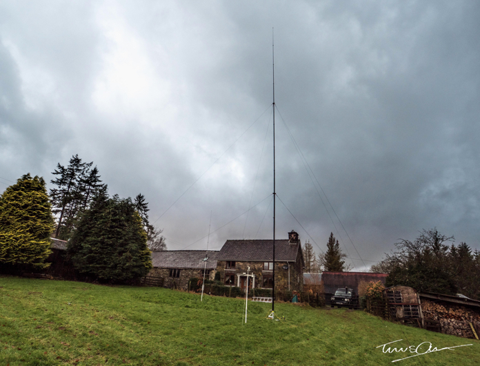
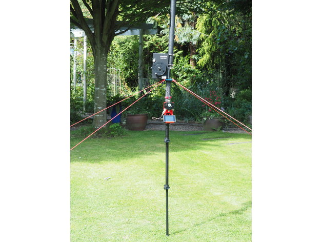
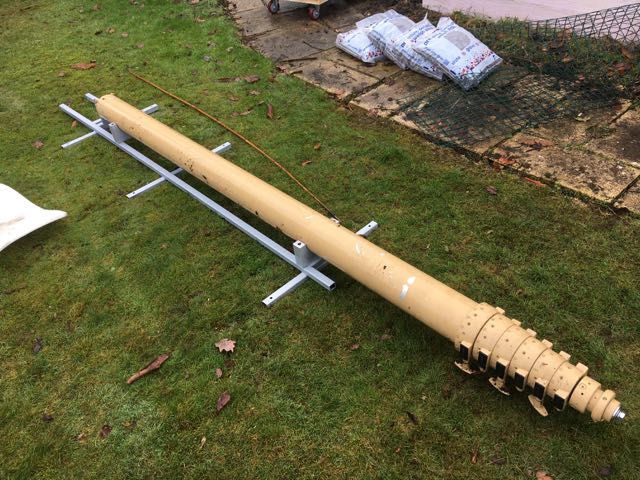
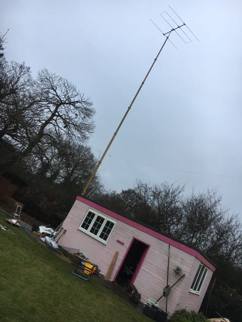
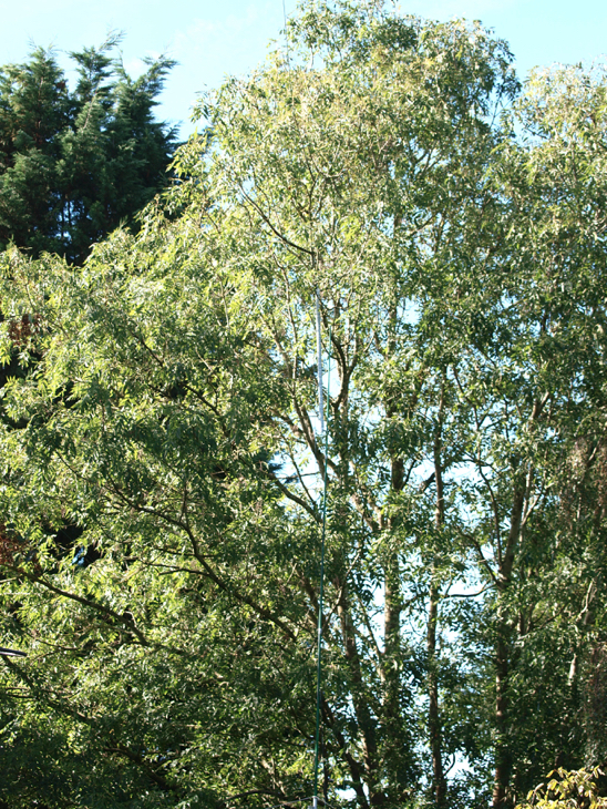
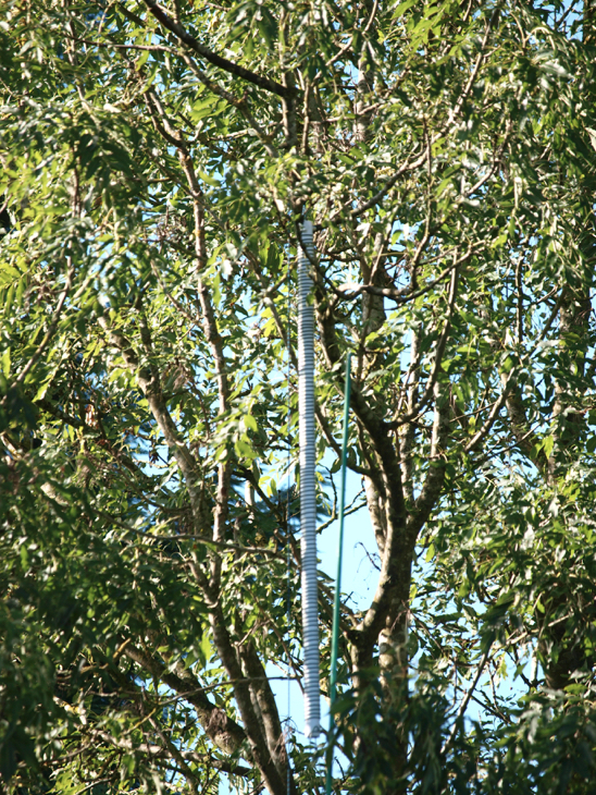
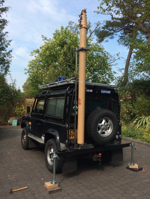
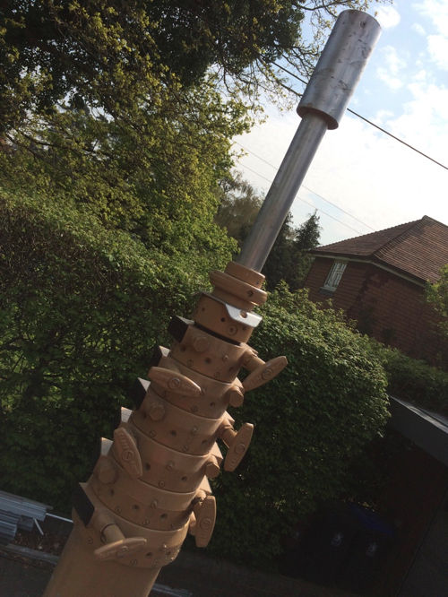
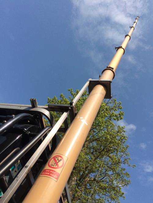
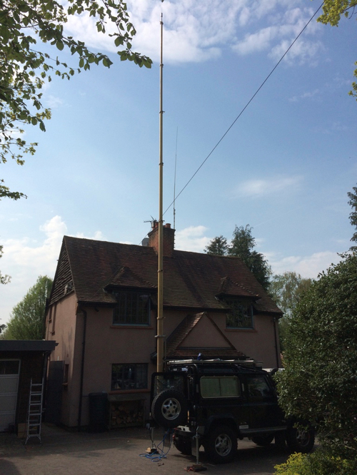
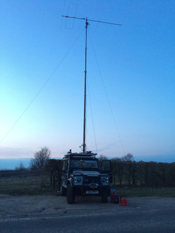
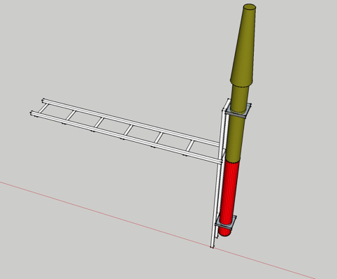
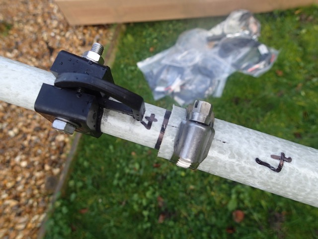
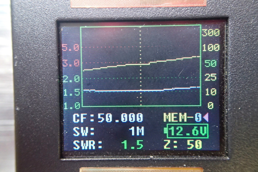
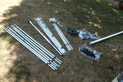
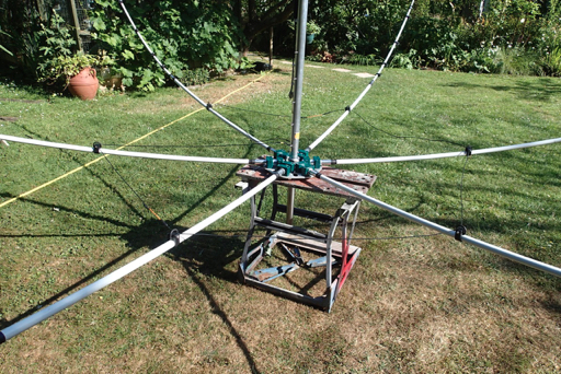
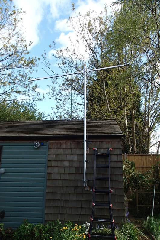
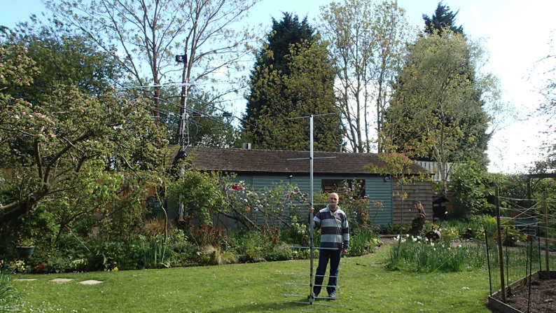
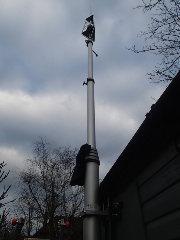
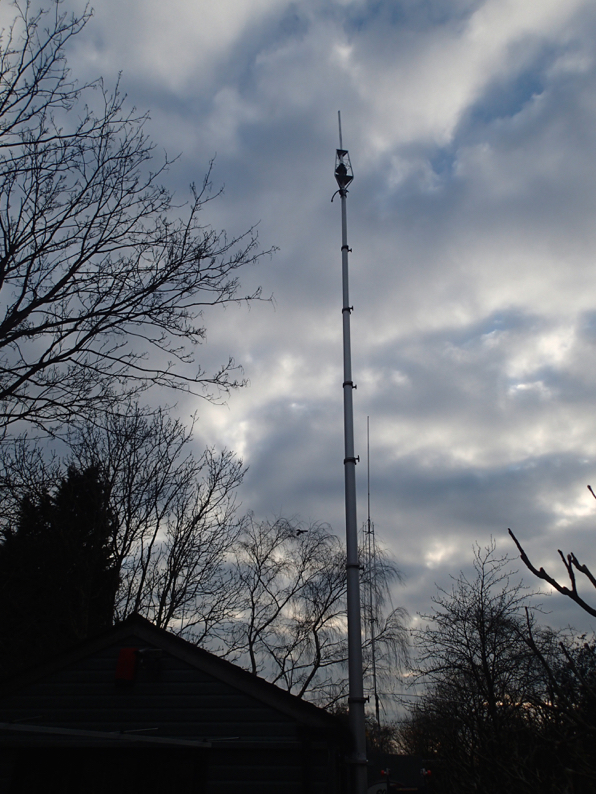
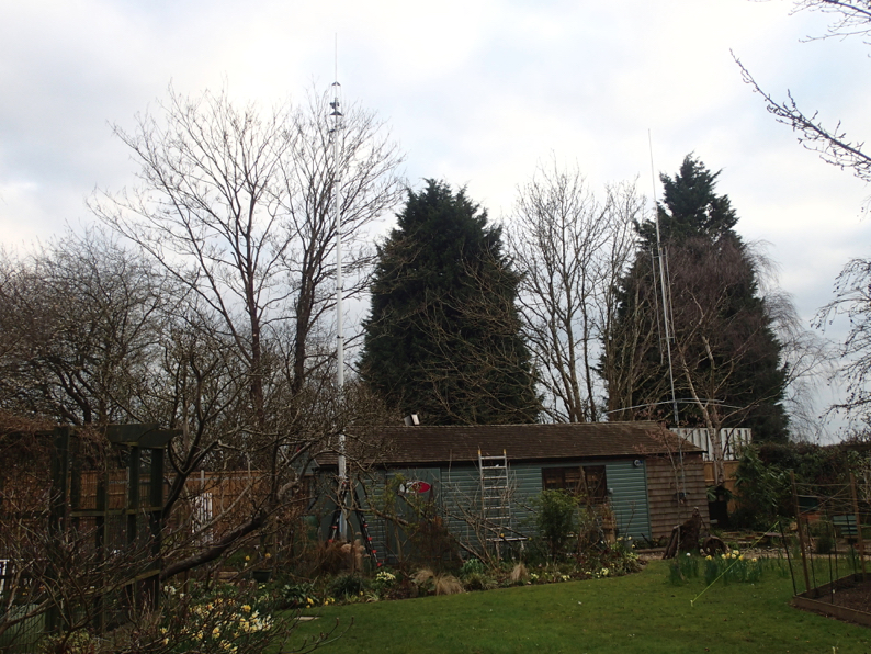
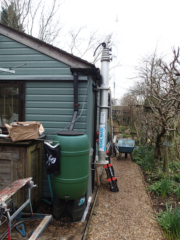
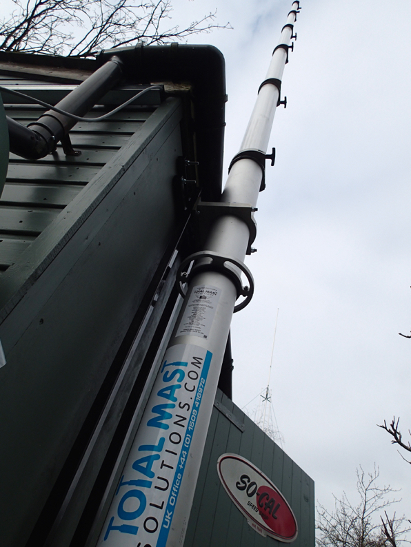
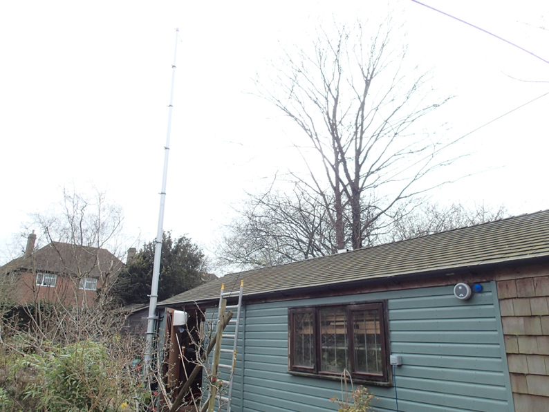
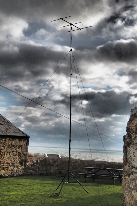
The testing went well for the new 80m vertical to be deployed in the Bouvet chase down in Cornwall.
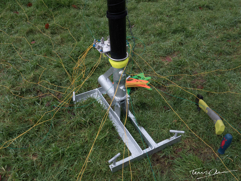
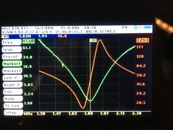
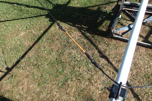
It is an 18m spiderpole with a 1/4 wave element wound round it an loads of radials. It was spot on for the bottom of the band which is where we will work them if at all, I suspect
With 80w and at the bottom of a called we had no problems working the states so there is hope.
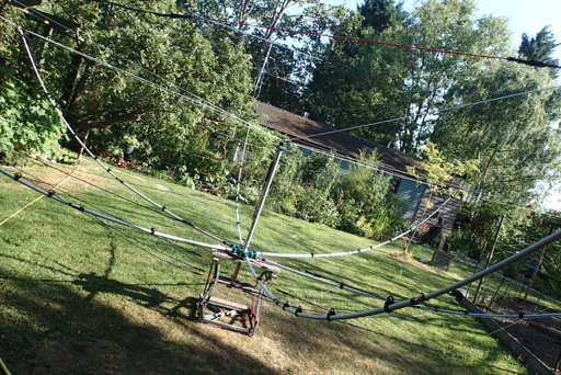
Thanks to SUR for spending time helping me with this one and providing the Welsh gales to test it’s stability.
Comments
New 6m beam for the UKAC
24/07/17 08:43
6M Beam
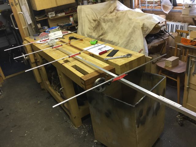
I have been chatting with my pal Terry about what to do for the 6m UKAC next year (when the Nordic scoring system has been sensibly been adopted) and my thoughts turned to making a more portable solution to my 5 ele LFA. More portable in the sense of the time it takes to put it together.
So taking clues from the 2M ones that I have made and written about before I am going to have a go at a 6 or 7 ele DK7ZB version. So the question was to make some stronger spacers that the elements can clip into. Cue the new 3D printer.
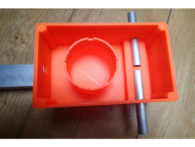
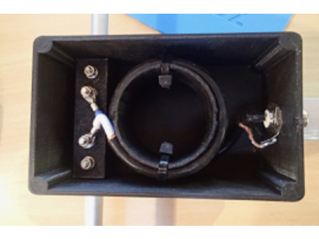
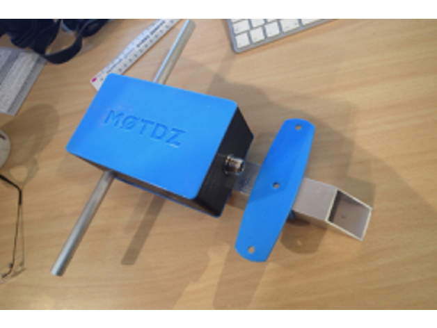
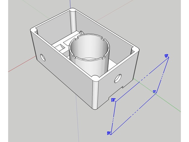
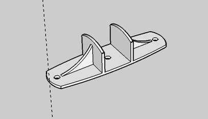
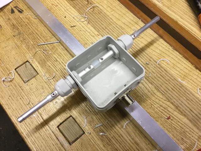
I started with the driven element box which is going to be something like this with a core built in to wind a choke on.
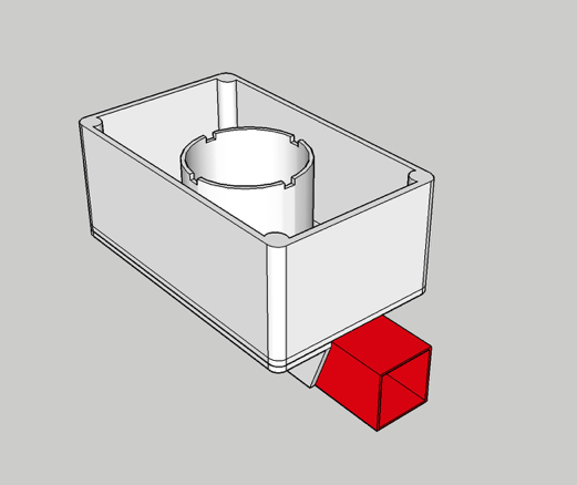
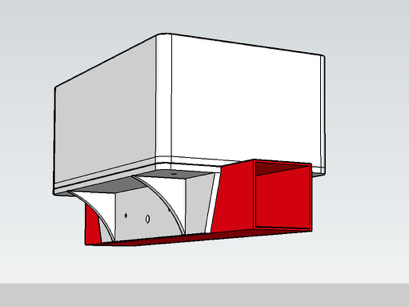
And for a first attempt it turned out pretty well
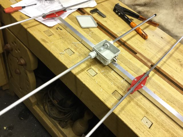
I will probably have a go at printing a bit to hold the driven elements in as well.
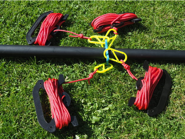
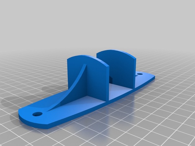
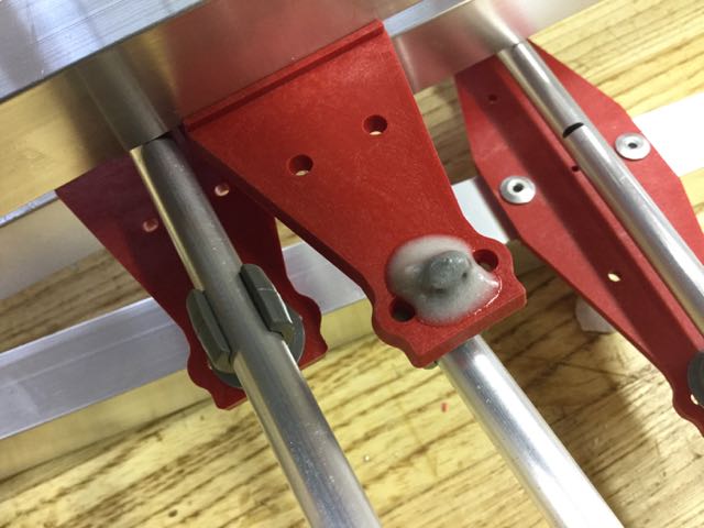
This is the idea for the other passive element clamps which will have a 10mm pipe clamp on the top
more as it happens !!
I have been chatting with my pal Terry about what to do for the 6m UKAC next year (when the Nordic scoring system has been sensibly been adopted) and my thoughts turned to making a more portable solution to my 5 ele LFA. More portable in the sense of the time it takes to put it together.
So taking clues from the 2M ones that I have made and written about before I am going to have a go at a 6 or 7 ele DK7ZB version. So the question was to make some stronger spacers that the elements can clip into. Cue the new 3D printer.
I started with the driven element box which is going to be something like this with a core built in to wind a choke on.
And for a first attempt it turned out pretty well
I will probably have a go at printing a bit to hold the driven elements in as well.
This is the idea for the other passive element clamps which will have a 10mm pipe clamp on the top
more as it happens !!
Shhhhh.
06/03/17 08:04
Charlie has brought me a WSPRlite from Sotabeams
Apart from having to find one of those old fashioned Windoze computers to set it up, it is a breeze and works a treat.
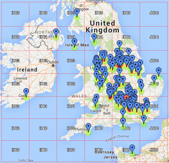
I am sending 200mW up my delta loop at the moment and in a day have been spotted in all these locations
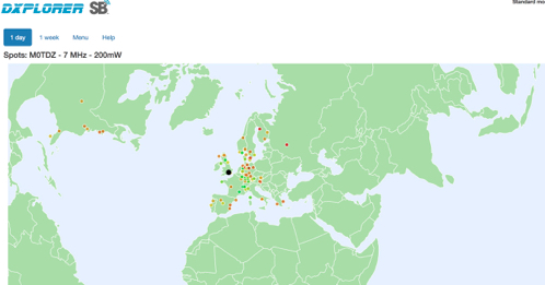
This is a really useful tool. Check it out.
Apart from having to find one of those old fashioned Windoze computers to set it up, it is a breeze and works a treat.
I am sending 200mW up my delta loop at the moment and in a day have been spotted in all these locations
This is a really useful tool. Check it out.
New Aerials
31/01/17 14:52
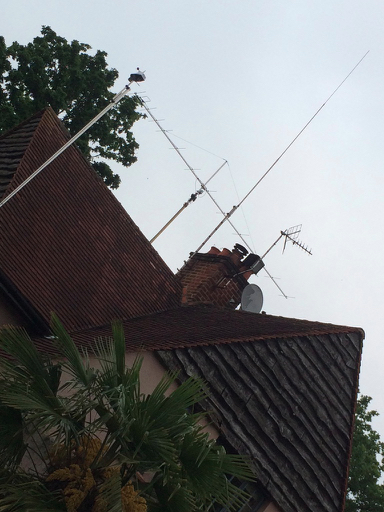
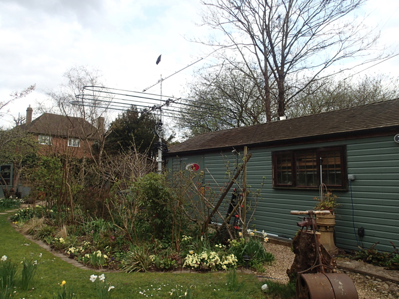
Are up and look as if they are working now - despite having to put the scaffold up again to sort out the connector on the pre amp.
Changing the Beams
16/01/17 08:28
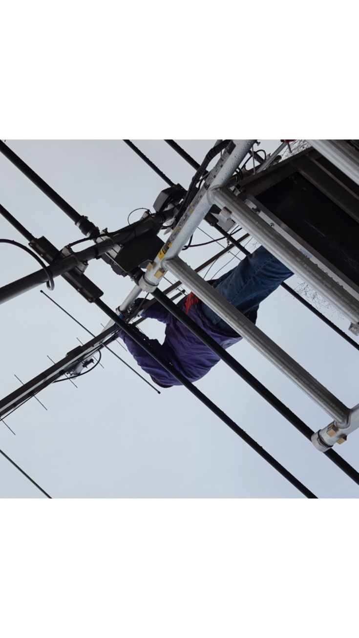
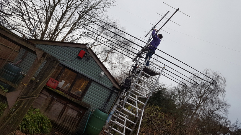
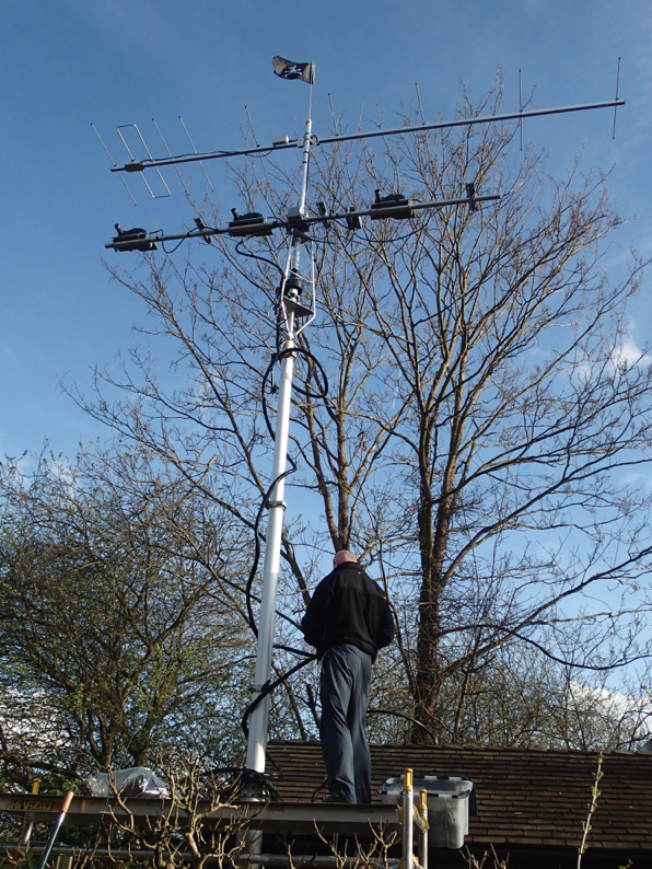
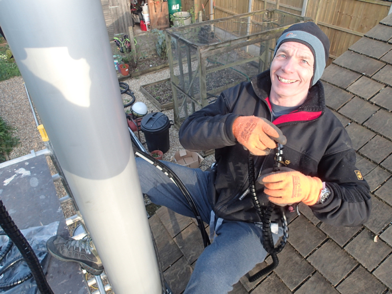
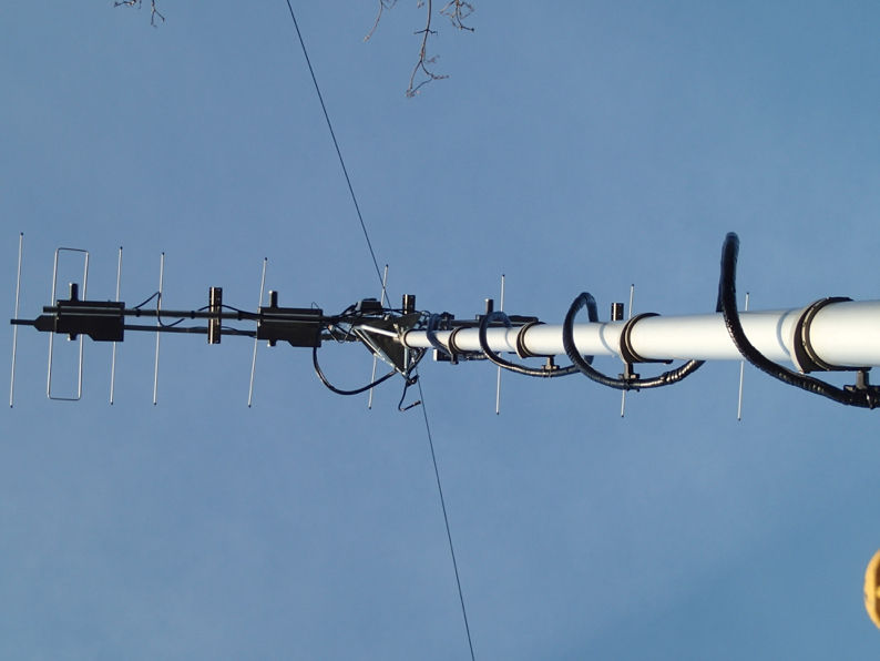
Here we are on a cold winters day in the rain up the scaffold swapping the 2m beam for a DK7ZB 10 ele and adding on a Dual antennas 14 ele 70cms. With with pre amps.
Looks like the 70cms is k by the B*** connectors on the 2M and doing this usual not quite making is so the scaffold needs to go up again.
Thanks to SUR for coming round and helping. It makes all the difference.
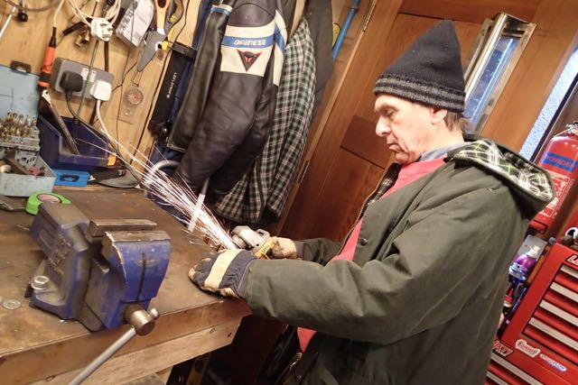
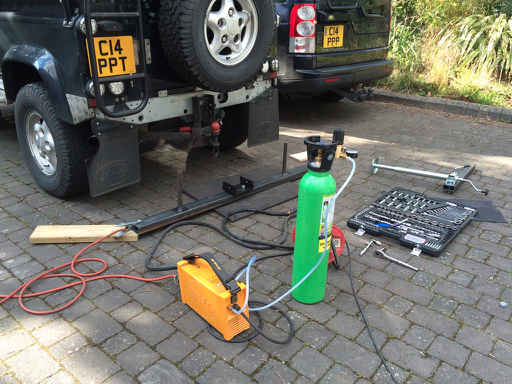
Another Monster Mast
08/01/17 18:54
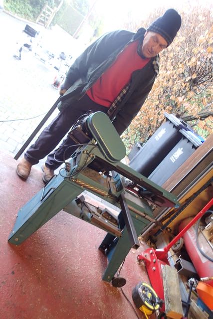
This time for Charlie.
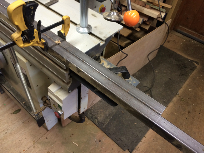
Wet started off cutting up all the 30x30x3mm section on the bandsaw
and laying to out
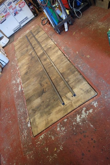
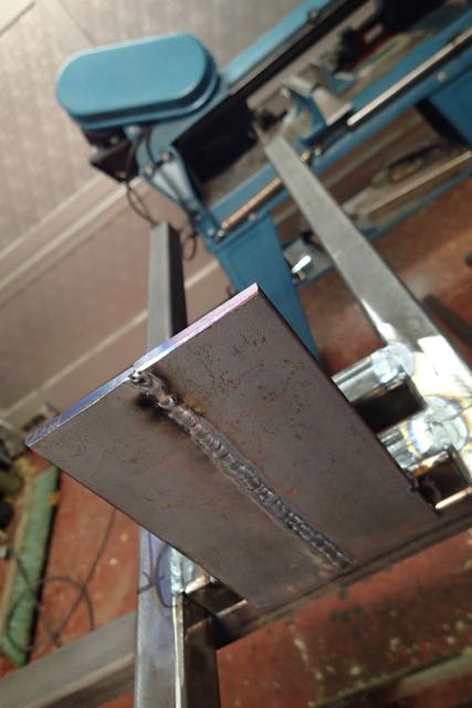
A bit of cleaning up
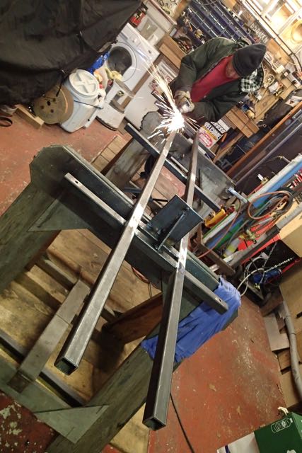
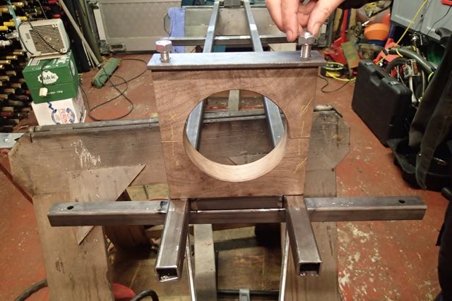
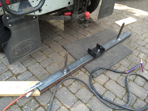
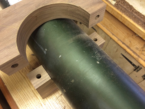
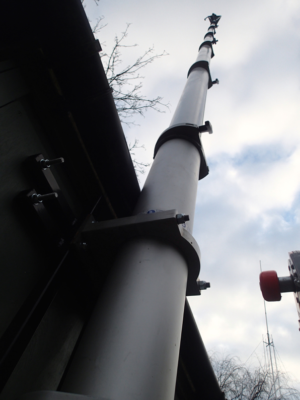
and welding it all together. Here is the base plate that the mast sits on
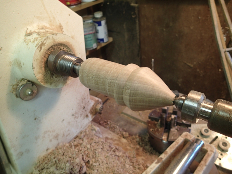
and the collar turned from walnut (posh!)
That was day one
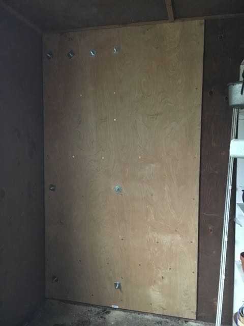
Sunday was erection day after fitting the ply to both sides of the wall and spraying the metalwork
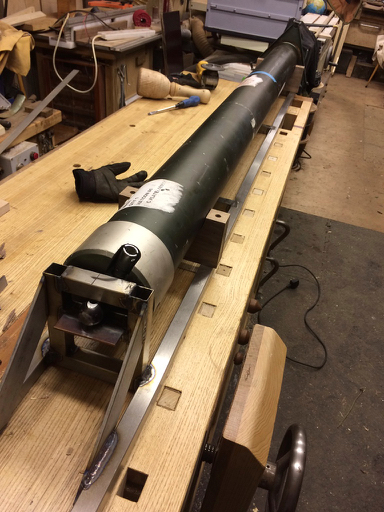
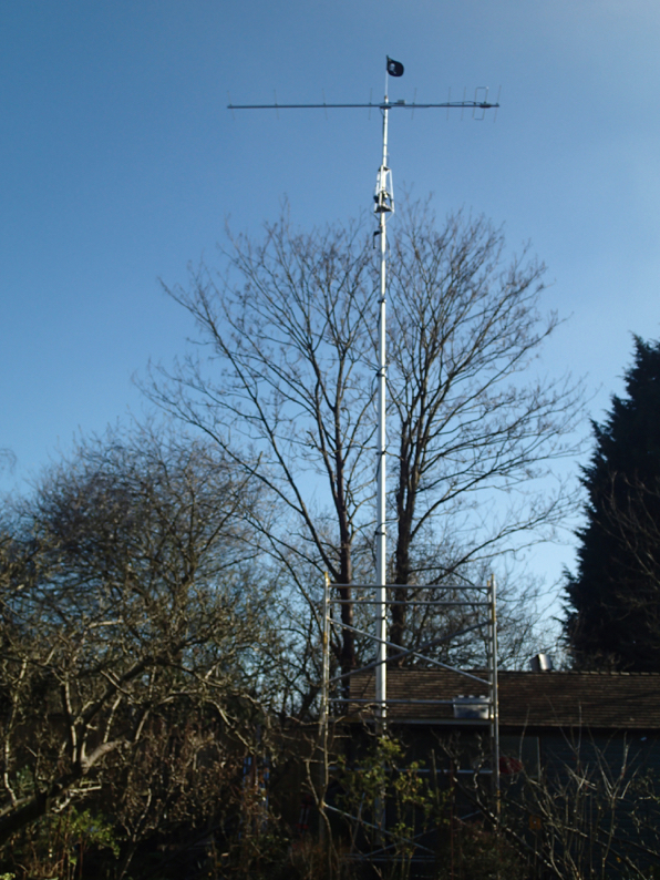
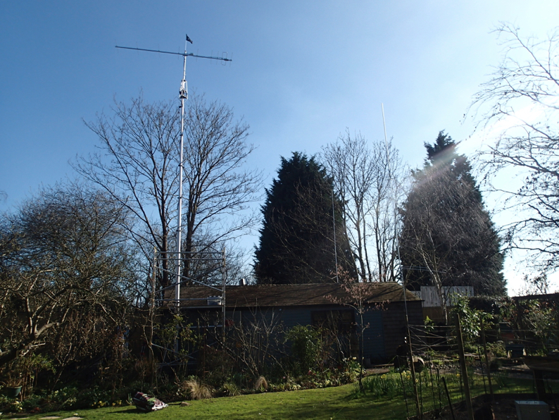
here it is on the frame
and here is the frame on the wall. bolted through with 10 and 12mm studding
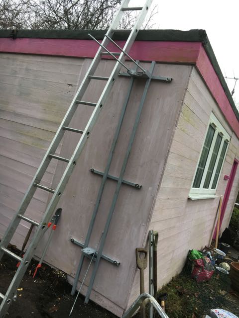
then the moment of truth
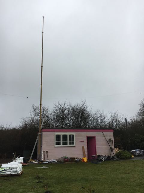
That’s 45’ to you sir
Wet started off cutting up all the 30x30x3mm section on the bandsaw
and laying to out
A bit of cleaning up
and welding it all together. Here is the base plate that the mast sits on
and the collar turned from walnut (posh!)
That was day one
Sunday was erection day after fitting the ply to both sides of the wall and spraying the metalwork
here it is on the frame
and here is the frame on the wall. bolted through with 10 and 12mm studding
then the moment of truth
That’s 45’ to you sir
Another StepIr
21/11/16 08:23
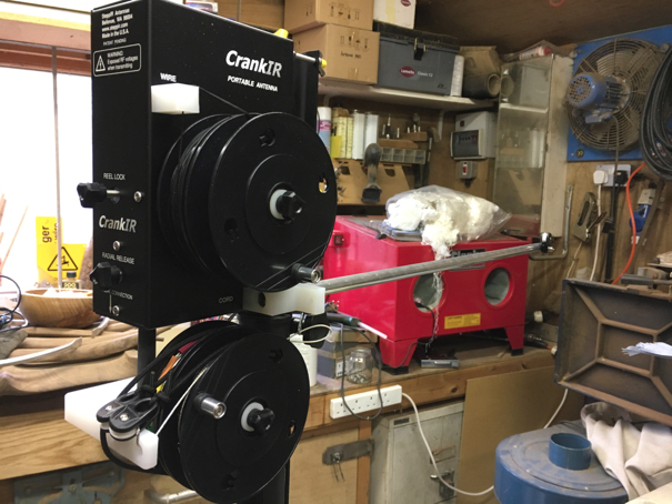
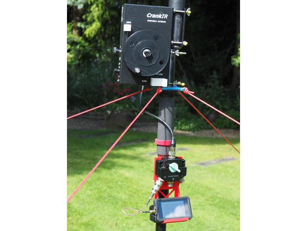
Here is the portable vertical CrankIr from StepIr.
At first test on a rainy winters day - it looks the business
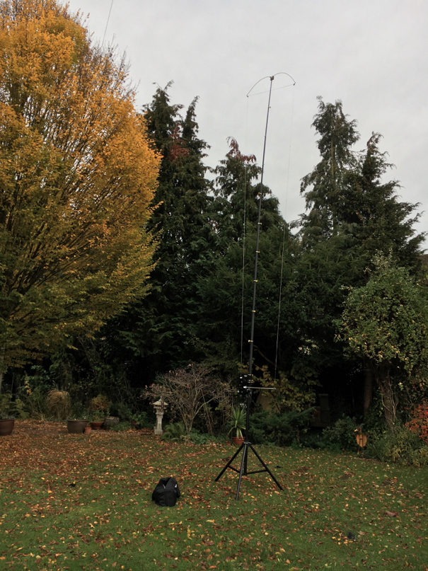
Here is is on 40m
Top Band Antenna
11/09/16 09:46
I made up the top loaded inverted L antenna that I circulated plans for and eventually got it up a tree.
It is quite hard to see
Which is good.
Here is the 5’ loading inductor closer up
And if you look carefully you can see the end fed wire and the top band one heading off to another tree
I had my first TB QSO with Andy YGB. Not DX but it works. dead easy to make as well at no cost.
Give it a go.
It is quite hard to see
Which is good.
Here is the 5’ loading inductor closer up
And if you look carefully you can see the end fed wire and the top band one heading off to another tree
I had my first TB QSO with Andy YGB. Not DX but it works. dead easy to make as well at no cost.
Give it a go.
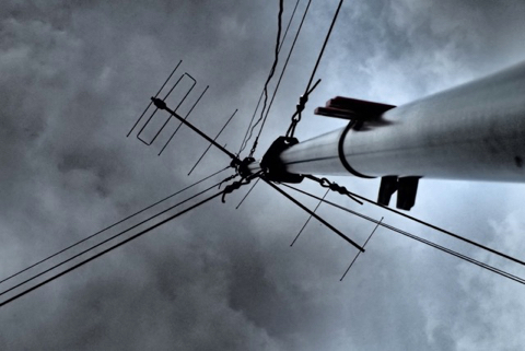
Monster Yagi
13/06/16 07:50
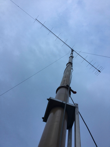
Yes It works.
Good news is that it's front to back is great and local stations do not bother it nearly as much. Given the site is no good working to the east I was happy with the results.
Good news is that it's front to back is great and local stations do not bother it nearly as much. Given the site is no good working to the east I was happy with the results.
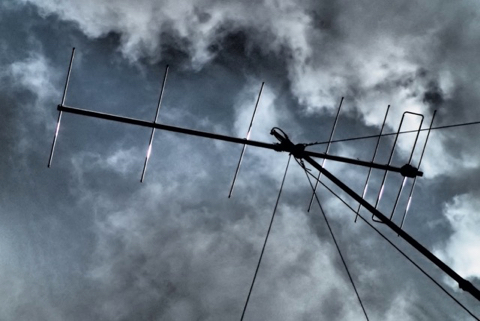
Let's Try that Again
04/06/16 19:00
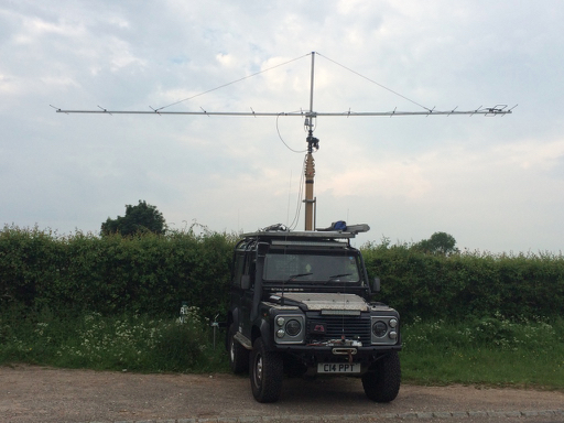
Remember when I fell off the car with the monsterYagi. That spurred me into a pneumatic solution.
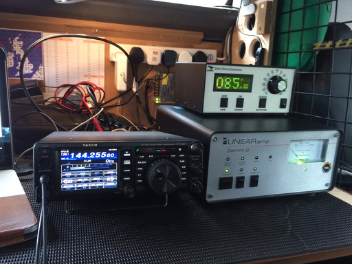
Well it’s time to resurrect it for the Tuesday 144Mhz. I am also trying a different approach on the radio having been told off for having a wide signal. So the plan is to run the radio at 5 watts into the Gemini and let that do the work.
So today was test day and I have to say, apart from looking massive, it works a treat. I did some tests with UK stations and then worked five or six ON stations and some F portables who were on some sort of field day contest. Lets see if is works for the UKAC and is not too pointy.
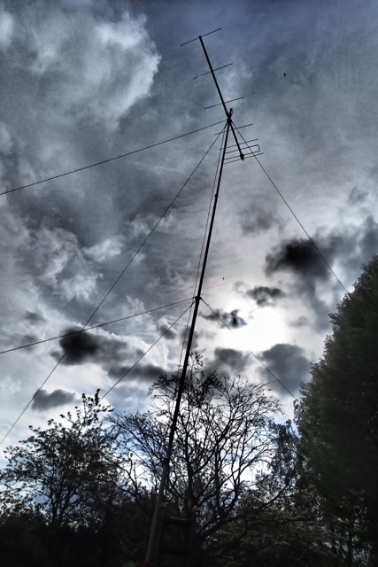
Mast History
14/05/16 08:30
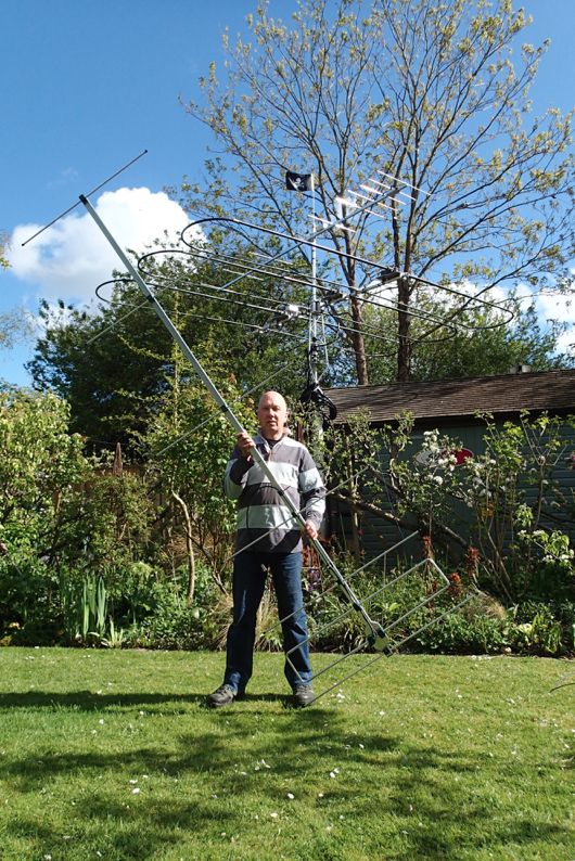
144Mhz 7ELE Portable
12/05/16 12:38
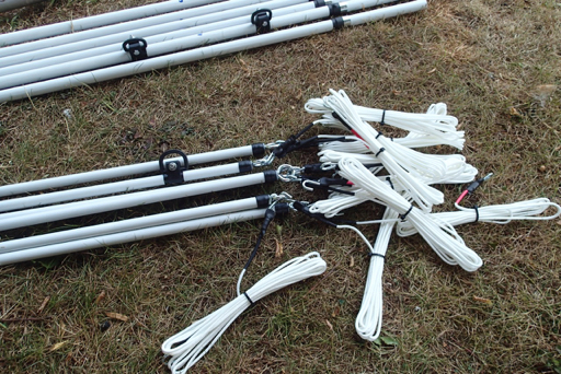
Here it is……Not spoken to anyone on it yet mind you. But it is 2m after all !
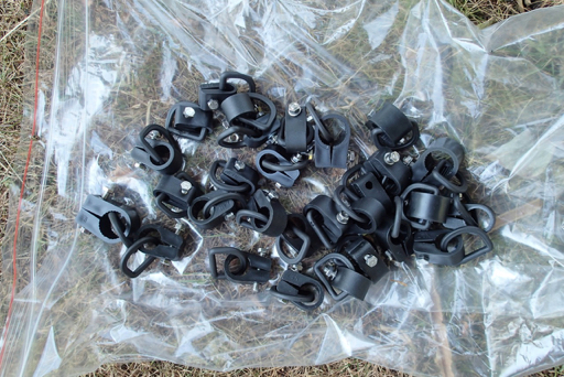
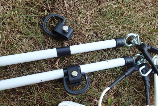
Packs up nice and neat
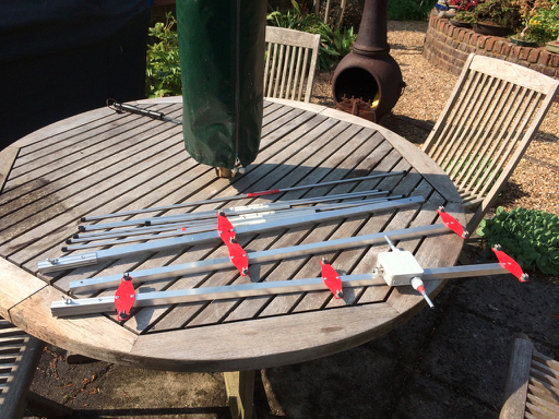
3 boom elements
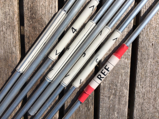
Labels for the elements
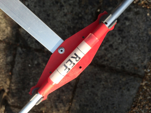
Clip in
pins to hold the driven elements on
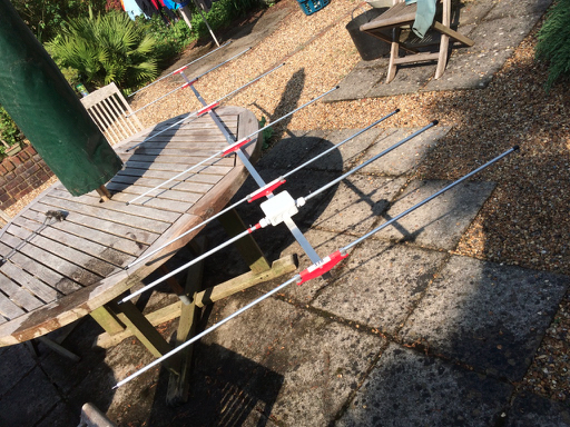
together in seconds
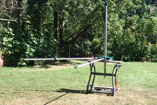
Up for testing
I need to check the geometry as its resonant a bit higher up the band. But fine all the same.
Thanks to Steve for the element clamps bits there is a link in the last post.
Packs up nice and neat
3 boom elements
Labels for the elements
Clip in
pins to hold the driven elements on
together in seconds
Up for testing
I need to check the geometry as its resonant a bit higher up the band. But fine all the same.
Thanks to Steve for the element clamps bits there is a link in the last post.
Lightweight Yagi
09/05/16 08:02
For all those who have asked here is the ink to the fantastic plates that Steve has had made for the Nuxcom kits.
MOUNTING PLATE
I have had a go at making up the driven element as per the Nuxcom plans but am not happy with it as it is a bit wobbly. So I am looking again at Steve's version and am going to have a go at adapting the box with a mounting plate to beef it up a bit.
Check it out HERE
MOUNTING PLATE
I have had a go at making up the driven element as per the Nuxcom plans but am not happy with it as it is a bit wobbly. So I am looking again at Steve's version and am going to have a go at adapting the box with a mounting plate to beef it up a bit.
Check it out HERE
Huge Erection - Again
07/05/16 11:24
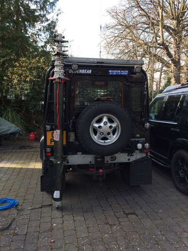
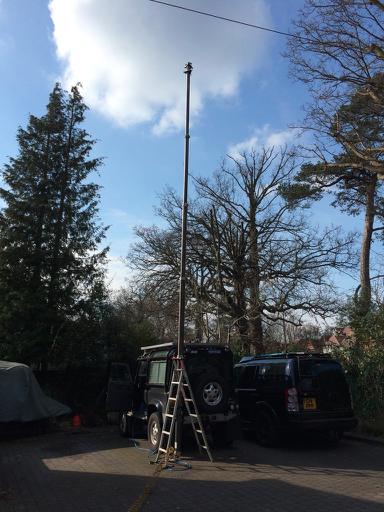
So after yesterdays fitting of the mast it is time to give it a go.
Yes it works. And is still up without the compressor after an hour. Excellent.
Yes it works. And is still up without the compressor after an hour. Excellent.
Bigger Mast
07/05/16 08:55
Not happy with the problem seal on the Racal mast I stumbled across a nearly new Clark mast on ebay.
It turns out to be one of a set that were purpose built for a particular security operation and painted in desert colours. It looks like thy were designed to be linked together and all pump up together.
Anyway it is a 13.5m with a 40Kg headload. for a fraction of the new price , that will do nicely. Taller than a Scam and nearly up to the same headload.
I went to Somerset to collect and it only just fitted diagonally in the Disco.
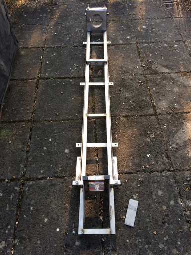
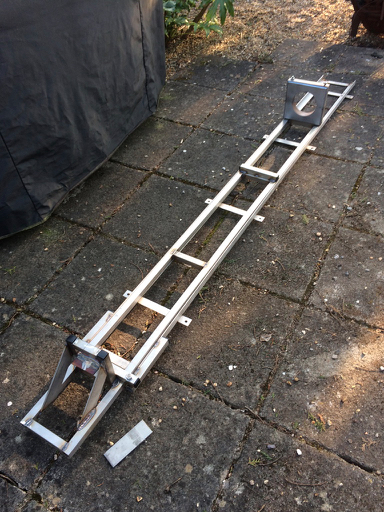
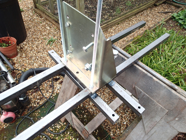
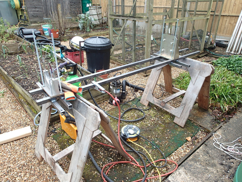
Then set about modifying the carriage for the original mast.
By adding a bit on the base
Here is is tacked up
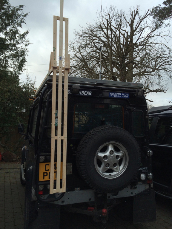
Now to wait till I can get someone to help me onto the car with it.
It turns out to be one of a set that were purpose built for a particular security operation and painted in desert colours. It looks like thy were designed to be linked together and all pump up together.
Anyway it is a 13.5m with a 40Kg headload. for a fraction of the new price , that will do nicely. Taller than a Scam and nearly up to the same headload.
I went to Somerset to collect and it only just fitted diagonally in the Disco.
Then set about modifying the carriage for the original mast.
By adding a bit on the base
Here is is tacked up
Now to wait till I can get someone to help me onto the car with it.
2M Beam Progress
02/05/16 12:05
We are pretty much there with the beam until the coax arrived from Nuxcom.
i have the elements set on the beam
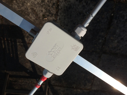
and the guts of the driven element done
I have made the elements removable.
Yes the clever ones among you would spot that I could have made it even more compact by fixing the stubs to the elements as opposed to the centre!
Next Time
I have mixed some epoxy with microbaloons to glue in the element holders
They are a pretty snug fit and hold the elements well.
Next stage is the driven element matching stub.
i have the elements set on the beam
and the guts of the driven element done
I have made the elements removable.
Yes the clever ones among you would spot that I could have made it even more compact by fixing the stubs to the elements as opposed to the centre!
Next Time
I have mixed some epoxy with microbaloons to glue in the element holders
They are a pretty snug fit and hold the elements well.
Next stage is the driven element matching stub.
Beam Hitch
02/05/16 08:07
Slight hitch in the plans..
The Nuxcom beam uses a matching stub and there are two options I went for the RG175 option at slight additional cost as this can fit into the box for the radiating element. That keeps it neat and particularly for the purpose that I am looking to use it will make it easier to carry and avoid snagging the stub which would be attached to the boom if not using the RG175.
I thought ordered the RG175 option but it didn’t get transferred onto the delivery so I will need to re order this and wait to work finish the beam.
My fault, I am sure, for not double checking the paperwork…….damn
Anyway we will get on with rising the element holders and do what we can on the radiator whilst we wait.
portable 2m beam
29/04/16 19:13
So having taken a poll and emailed a few people in the know I have set about building a couple of kits from Nuxcom in Germany to theDK7ZB designs.
NUXCOM
I have some of Steve’s special boom spacers and some 8mm pip clips so that I can follow Steve’s method for quick set up.
So far the trial fit looks as if it will work fine.
There is no time to continue today so I will be back…..as someone famous once said.
NUXCOM
I have some of Steve’s special boom spacers and some 8mm pip clips so that I can follow Steve’s method for quick set up.
So far the trial fit looks as if it will work fine.
There is no time to continue today so I will be back…..as someone famous once said.
New Compressor
11/04/16 08:17
Here is the new ViAir compressor from Matt Savage - great service - it arrived in a day
This is to replace the Arb one that was not really up to the task. This is a 100% duty version which hopefully will do the job.
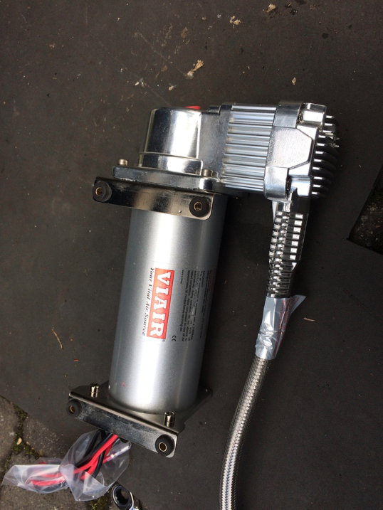
This is to replace the Arb one that was not really up to the task. This is a 100% duty version which hopefully will do the job.
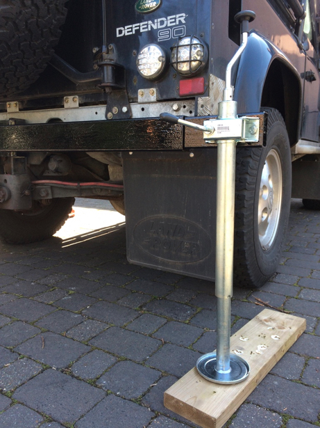
Stabilisers
03/04/16 17:35
Here are the (badly) painted stabilisers to stop the car rocking on its suspension.
And a handy idea, for making sleeves to increase the diameter of tube.
In this case the HexBeam so that it will slot into the rotator on the new mast.
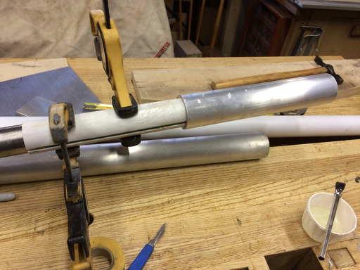
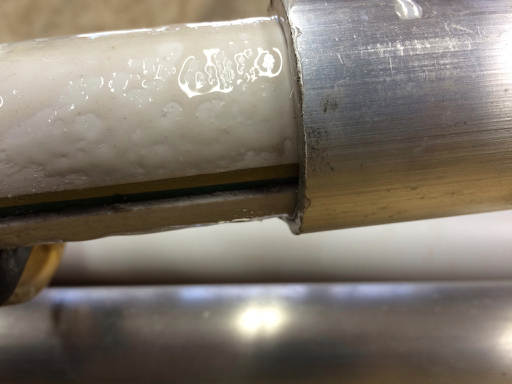
Cut some plastic tube to makeup the difference and split in two.
Mask the gaps and epoxy it into the scaffold tube and leave to dry overnight.
It works! I will need to drill a bolt hole to stop it rotating but that’s it.
And a handy idea, for making sleeves to increase the diameter of tube.
In this case the HexBeam so that it will slot into the rotator on the new mast.
Cut some plastic tube to makeup the difference and split in two.
Mask the gaps and epoxy it into the scaffold tube and leave to dry overnight.
It works! I will need to drill a bolt hole to stop it rotating but that’s it.
Air to Spare
31/03/16 20:06
This is now moving from a radio blog to a Landrover modding blog I fear.
Two deliveries today. One from Matt Savage which had the air reservoir
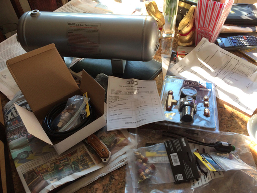
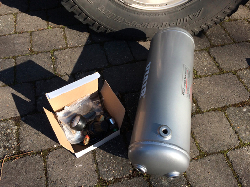
I have an ARB compressor in the truck but that doesn’t have enough reserve to pump the mast up. So I am adding 2 gallon Vair tank. That goes under the drivers side.
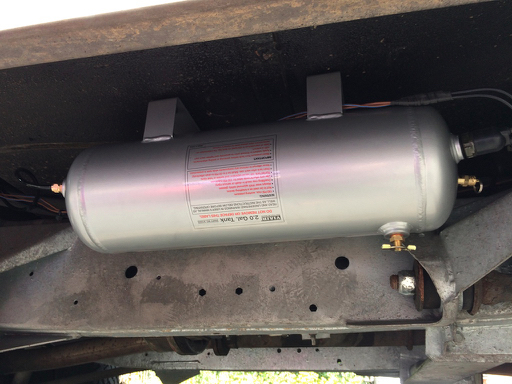
The pump feeds the tank and I have moved the pressure switch to the tank from the pump.
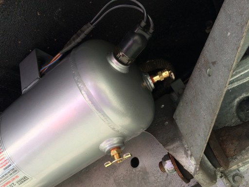
The tank also has a drain valve and a pressure release valve as well
Here is the pump with the plastic pressure hose going off to the tank
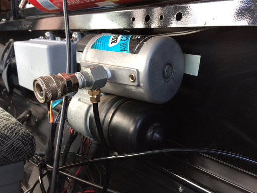
Now the pump is not that great a capacity and takes a couple of minutes to fill the reservoir so we will see tomorrow how it works with the mast.
The tank feeds another outlet, this time regulated, at the rear
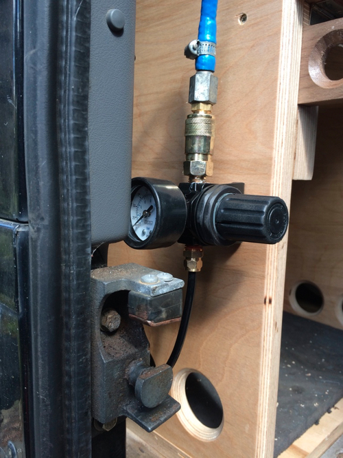
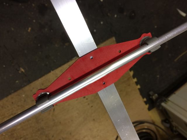
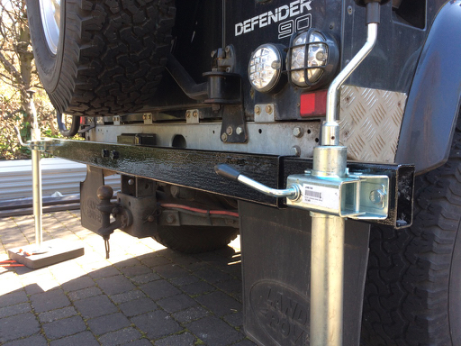
Then the steel came for the supports to stop the truck rocking so much.
the idea being that it pins to the tow bar thing and has a couple of bars that go into the jacking points
Its being painted overnight so hopefully tomorrow we can test it all together and decide if another higher volume pump is needed.
Two deliveries today. One from Matt Savage which had the air reservoir
I have an ARB compressor in the truck but that doesn’t have enough reserve to pump the mast up. So I am adding 2 gallon Vair tank. That goes under the drivers side.
The pump feeds the tank and I have moved the pressure switch to the tank from the pump.
The tank also has a drain valve and a pressure release valve as well
Here is the pump with the plastic pressure hose going off to the tank
Now the pump is not that great a capacity and takes a couple of minutes to fill the reservoir so we will see tomorrow how it works with the mast.
The tank feeds another outlet, this time regulated, at the rear
Then the steel came for the supports to stop the truck rocking so much.
the idea being that it pins to the tow bar thing and has a couple of bars that go into the jacking points
Its being painted overnight so hopefully tomorrow we can test it all together and decide if another higher volume pump is needed.
Secret Weapon
23/03/16 00:07
The new Secret Weapon was tested today after all the welding. and it seems to work.
The compressor was a bit iffy but the mast seals seem to be bedding in.
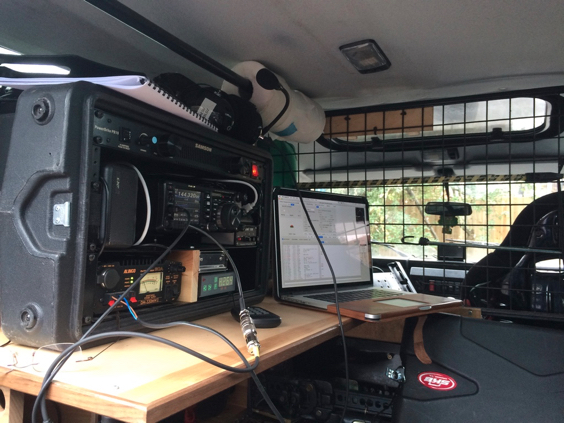
operating position is a “little” cramped
Results were pretty good the little bit of extra height makes a bit of a difference. Not that much though compared to last month.
The compressor was a bit iffy but the mast seals seem to be bedding in.
operating position is a “little” cramped
Results were pretty good the little bit of extra height makes a bit of a difference. Not that much though compared to last month.
Car Mast carriage
13/03/16 17:54
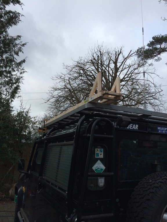
It’s been a long job but once the bolts for the roof rack arrive it can be tested.
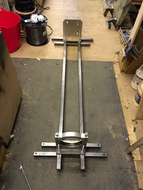
Here is the principle mocked up in wood.
I looked at getting the mountain plate for the bottom and the top mount from TMS and Clark. TMS don’t do them and Clark were going to cost more than the mast.
So I turned up the top one in walnut. You are not relying on the wood to hold it all together there are some stainless rods for that
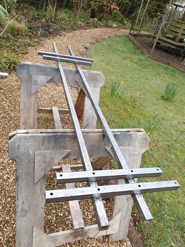
The rest is welded up in stainless 25mm box sections with some 30x30 angle for the sliding rail things.
Not doing much welding it amazes me how much to all moves when you weld it. Hence the sliding bit, at the moment, is not sliding as well as it might.
Now to find some stabilisers to stop the car rocking from side to side
Here is the principle mocked up in wood.
I looked at getting the mountain plate for the bottom and the top mount from TMS and Clark. TMS don’t do them and Clark were going to cost more than the mast.
So I turned up the top one in walnut. You are not relying on the wood to hold it all together there are some stainless rods for that
The rest is welded up in stainless 25mm box sections with some 30x30 angle for the sliding rail things.
Not doing much welding it amazes me how much to all moves when you weld it. Hence the sliding bit, at the moment, is not sliding as well as it might.
Now to find some stabilisers to stop the car rocking from side to side
Mast errr Full
03/03/16 16:53
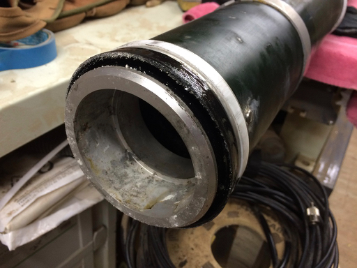
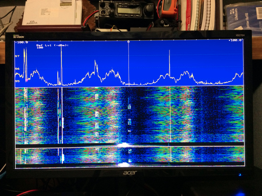
Ok we have the mast here and have tested it. there are some leaks so i have stripped it to get the sand from Afghanistan out.
The seals look pretty good actually but there is some pitting in one of the tubes. Not enough to stop it going up but enough to make it not stay up. That should not be a problem with the fantastic over centre clamps.
So I have cleaned and re greased it and we will see how it performs.
If there is still an issue with the pitting then i am going to have a go at filling the pitting with epoxy, which might work?
I then need to set about the roof mounting system which I have mocked up in some softwood.
I have some stainless tube in the shed so that is going to be used for the supporting frame and then the sliding base will be made from some angle.
Oh and here is today’s interference artwork…..Nice
Time for a new Mast
27/02/16 09:40
In looking for another option apart from falling off the top of the car I have found a secondhand Racal pneumatic mast .
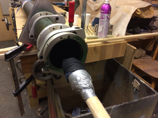
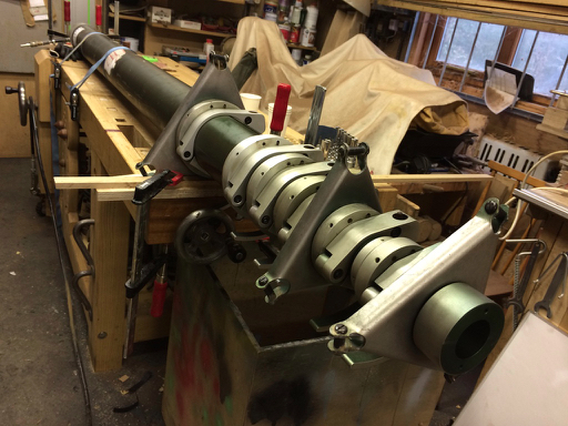
It needs a bit of a clean up and one of the seals seems a bit dodgy but for way aI paid for it that is not an issue.
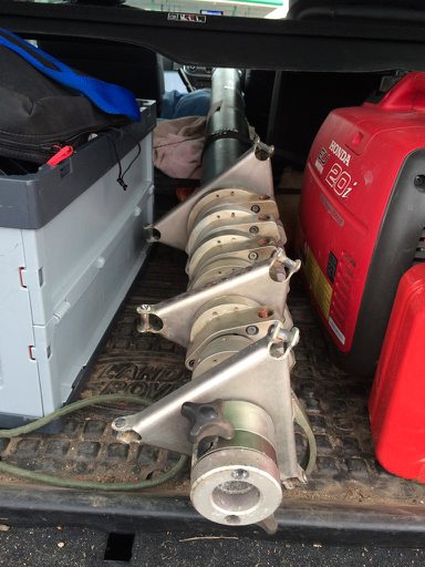
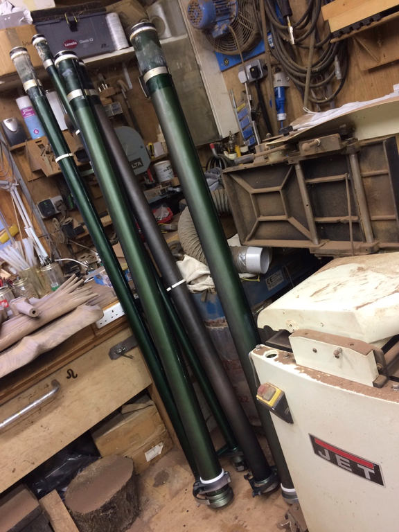
It is 2.6m closed
and I have yet to put up all the sections together. There are another 2 to go in this photo
12m total.
Now to design a roof mount system for it
It needs a bit of a clean up and one of the seals seems a bit dodgy but for way aI paid for it that is not an issue.
It is 2.6m closed
and I have yet to put up all the sections together. There are another 2 to go in this photo
12m total.
Now to design a roof mount system for it
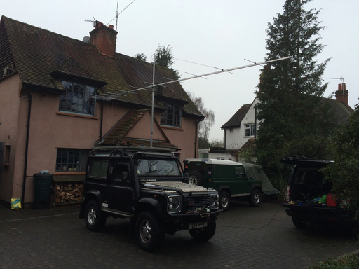
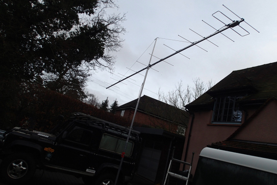
My That's a Whopper
23/01/16 17:55
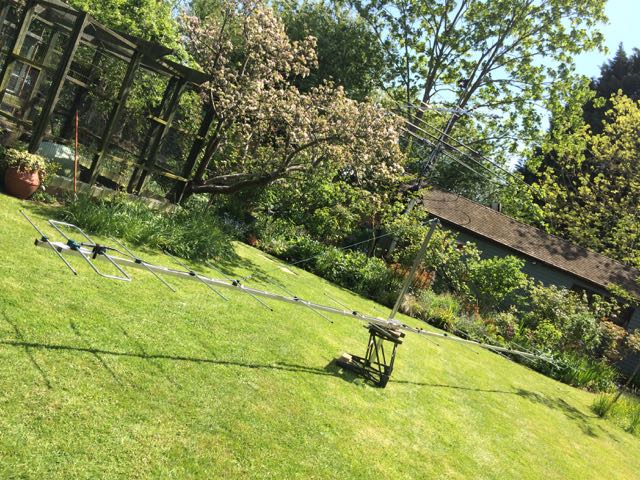
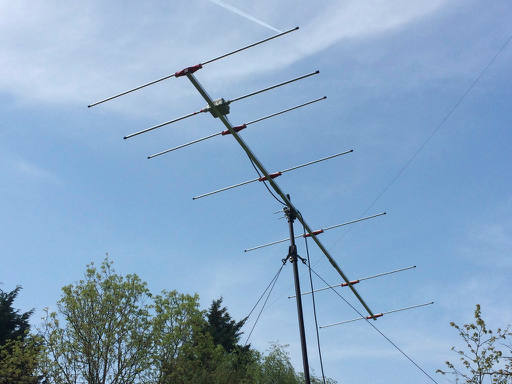
After the first 144mhz UKAC this year I found I was being out gunned with my 7 element LFA and a quick look at the competition shows they are all using higher gain antennas. So I had a chat with Justin of Innov Antennas fame and he has sent me the dimensions for a 14 and 13 element LFA yagi.
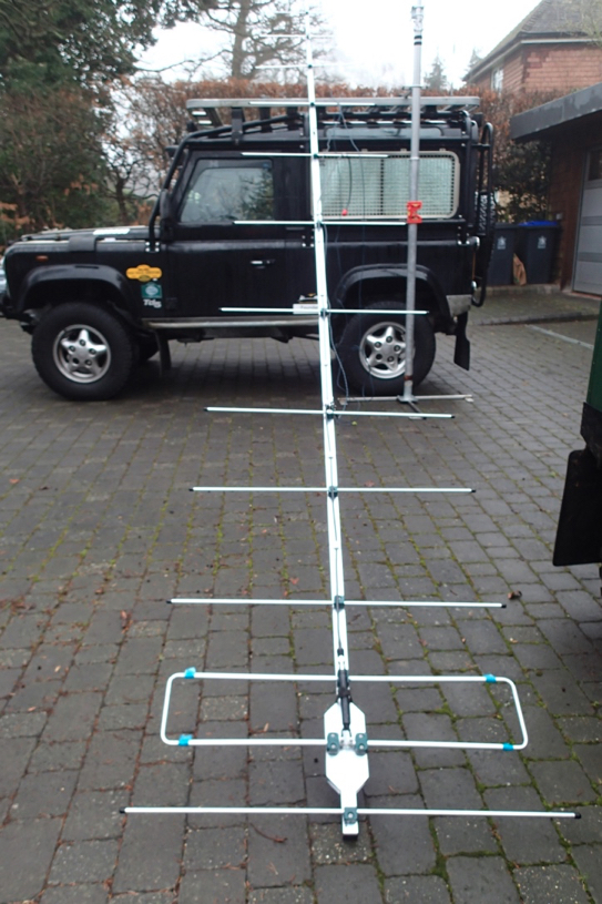
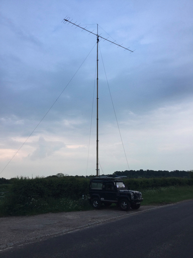
I went for the 13 element (lucky for some) which is 8m long. I have made it in 2 bits using the innovantennas 144mhz choke balun. I have added a new section to the mast that makes it easier to out the beam up a couple of supporting lines to keep it straight. In the driveway is is ok to put up and it will probably be just the wind that might be an issue at MP.
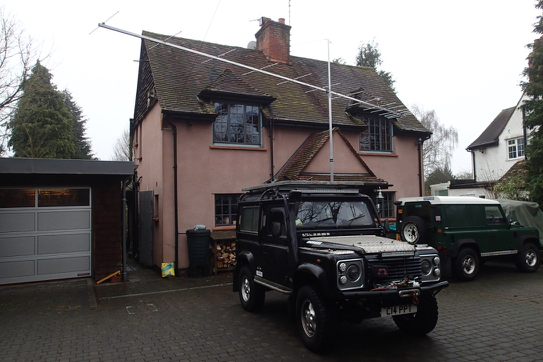
I have managed to get 1:1.3 VSWR over the SSB band. It wants to be fully resonant at 145 but i can’t seem to change that with different reflectors and directors.
Tuning consist of standing on a ladder and tapping the LFA elements in and out with a spare bit of aluminium. I expect the VSWR to change when i get it up to its full height but can only do so much without going out with it.
It will be interesting to see how it performs.
I went for the 13 element (lucky for some) which is 8m long. I have made it in 2 bits using the innovantennas 144mhz choke balun. I have added a new section to the mast that makes it easier to out the beam up a couple of supporting lines to keep it straight. In the driveway is is ok to put up and it will probably be just the wind that might be an issue at MP.
I have managed to get 1:1.3 VSWR over the SSB band. It wants to be fully resonant at 145 but i can’t seem to change that with different reflectors and directors.
Tuning consist of standing on a ladder and tapping the LFA elements in and out with a spare bit of aluminium. I expect the VSWR to change when i get it up to its full height but can only do so much without going out with it.
It will be interesting to see how it performs.
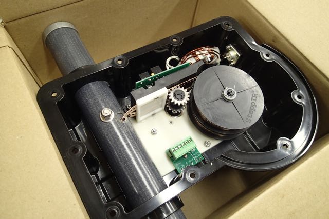
Green Heron
17/01/16 18:16
I use Spid rotators. One at home and one for the portable setup.
The controller for the one at home has been playing up loosing its place and as the Spid does not have endstops it is very easy for it to wind your coax and cables up round the mast. So I had a look at whatever everyone else was using and ordered a Green Heron controller from Jeff.
It arrived after our wales Trip, where incidentally the portable buddipole vertical worked ok. I got to the US and Canada on it. Anyway I digress. After confusing myself comparing the spid instructions with Jeff’s and an email dialogue with Jeff I finally got to connect the wires the right way round! Thinking too hard rather than just following instructions!
Anyway, Jeff’s support for us intermediate numpties is second to none. It still amazes me how people in this hobby provide such a brilliant service.
I will report on it after a bit more of a trial but so far I could not be happier with it and it had stayed synchronised with the beam- that’s the important thing.
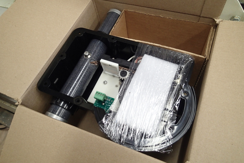
Here is whats inside it
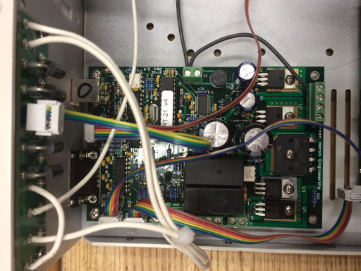
So what are the advantages over the standard Spid one.
1 there is a knob you can turn to point and shoot where you want the beam to point
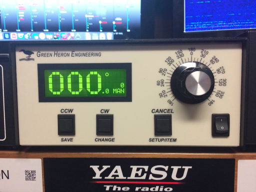
2 it is configurable to allow you to set end stops to stop it where you want
3 It ramps up to speed and slows down so it doesn’t shock the mast or antenna
4 it interfaces with Maclogger DX to show where the beam is pointing (see the green line on the compass - the grey one is where the station you are trying to contact is). It also gives you a green line on the world map to show where you are pointing
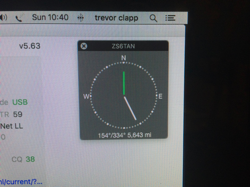
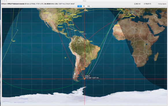
Here you can see the green line pointing at Bob VP8LP
There is a programme that goes with it but for that i need to invoke the dreaded windows so I will persevere with it for a bit as I might have to succumb to set the end stops as the rotator is set up, cable wise for 2 full rotations.
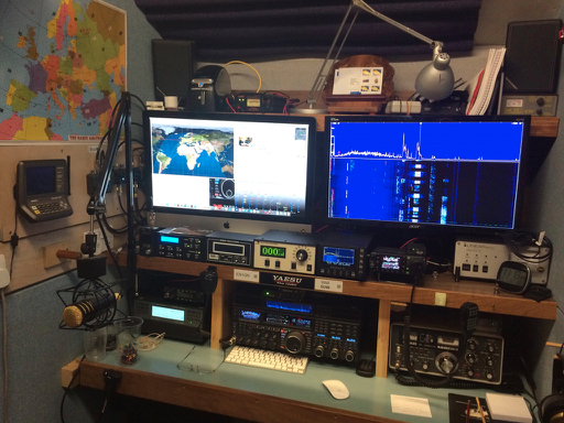
It connects to MLDX as before the only issue I am having is that it looses the USB connection when I turn the power off and on again. So I think i need to clear the Mac’s cache….or something technical like that.
Here it is in the shack. A quick test got us the US and Canada on 20m just as the band was vanishing. So all of you who know, from the UKAC, that I wang my beam around with gay abandon missing QSO’s from most of you, can be assured that the same is likely to happen from home as well!
The controller for the one at home has been playing up loosing its place and as the Spid does not have endstops it is very easy for it to wind your coax and cables up round the mast. So I had a look at whatever everyone else was using and ordered a Green Heron controller from Jeff.
It arrived after our wales Trip, where incidentally the portable buddipole vertical worked ok. I got to the US and Canada on it. Anyway I digress. After confusing myself comparing the spid instructions with Jeff’s and an email dialogue with Jeff I finally got to connect the wires the right way round! Thinking too hard rather than just following instructions!
Anyway, Jeff’s support for us intermediate numpties is second to none. It still amazes me how people in this hobby provide such a brilliant service.
I will report on it after a bit more of a trial but so far I could not be happier with it and it had stayed synchronised with the beam- that’s the important thing.
Here is whats inside it
So what are the advantages over the standard Spid one.
1 there is a knob you can turn to point and shoot where you want the beam to point
2 it is configurable to allow you to set end stops to stop it where you want
3 It ramps up to speed and slows down so it doesn’t shock the mast or antenna
4 it interfaces with Maclogger DX to show where the beam is pointing (see the green line on the compass - the grey one is where the station you are trying to contact is). It also gives you a green line on the world map to show where you are pointing
Here you can see the green line pointing at Bob VP8LP
There is a programme that goes with it but for that i need to invoke the dreaded windows so I will persevere with it for a bit as I might have to succumb to set the end stops as the rotator is set up, cable wise for 2 full rotations.
It connects to MLDX as before the only issue I am having is that it looses the USB connection when I turn the power off and on again. So I think i need to clear the Mac’s cache….or something technical like that.
Here it is in the shack. A quick test got us the US and Canada on 20m just as the band was vanishing. So all of you who know, from the UKAC, that I wang my beam around with gay abandon missing QSO’s from most of you, can be assured that the same is likely to happen from home as well!
Hex Beam Two
20/12/15 19:07
As you will have read I have a SP7DEX hex beam for portable use. Today we got to see the UK’s version of the G3TXQ design made in Wales by MWOJZE.

Martin had mine up for a while and because mine took ages to come from Poland opted for the Welsh version (his being Welsh made the language barrier less of a problem). He also has opted for the fantastic Spid rotator.
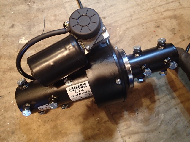
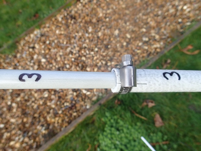
The hex beam is vet similar to the SP7DEX version the main differences being the way that he fibreglass spreaders join. The SP7DEX push together and the MW0LZE are held in place with jubilee clips. Both work well but the former better for portable operation if you are putting up and taking down a lot.
The tension stings are similar. No hooks this time but up to the job
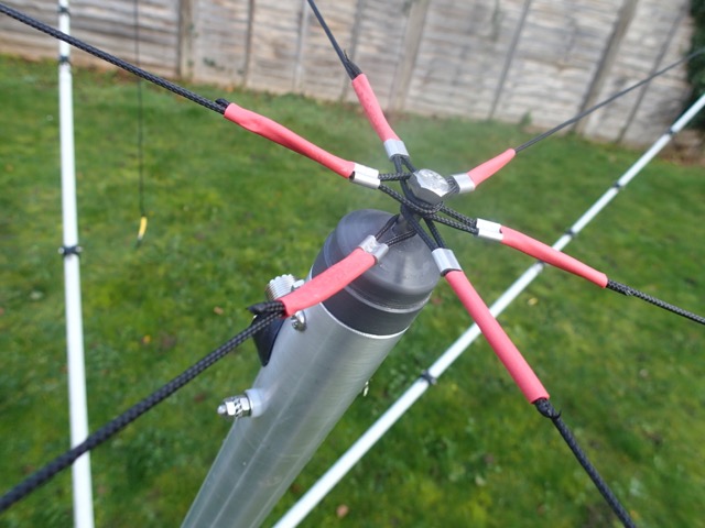
guides for the elements similar. you have to fiddle with the 20m ones but other than that an easy fit to get the wires through.
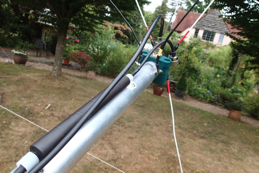
here is it wired up with the elements
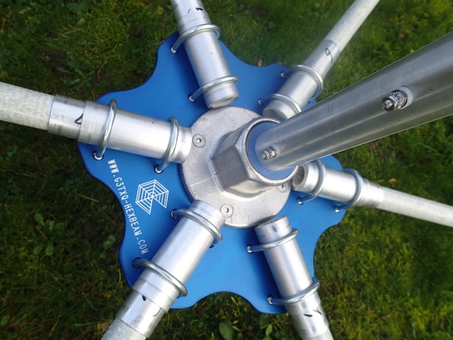
rotator goes onto a removable stub on the composite mast
Here is it with the co-ax in place and all wrapped up with self almagamating tape on the 259 connector
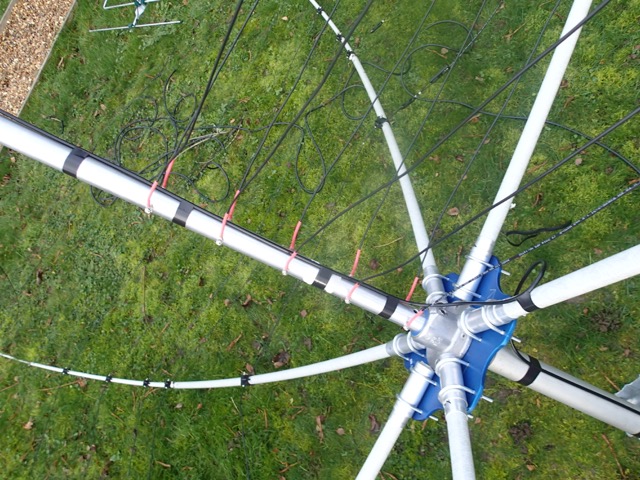
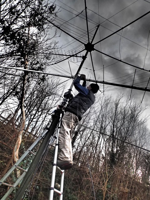
Under the hex is the 70cms and then Martin’s home made 2m 9 element LFA
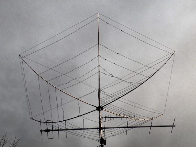
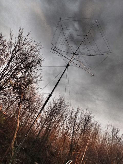
And it works first time call broke the pile up to a QSO to the US.
Martin had mine up for a while and because mine took ages to come from Poland opted for the Welsh version (his being Welsh made the language barrier less of a problem). He also has opted for the fantastic Spid rotator.
The hex beam is vet similar to the SP7DEX version the main differences being the way that he fibreglass spreaders join. The SP7DEX push together and the MW0LZE are held in place with jubilee clips. Both work well but the former better for portable operation if you are putting up and taking down a lot.
The tension stings are similar. No hooks this time but up to the job
guides for the elements similar. you have to fiddle with the 20m ones but other than that an easy fit to get the wires through.
here is it wired up with the elements
rotator goes onto a removable stub on the composite mast
Here is it with the co-ax in place and all wrapped up with self almagamating tape on the 259 connector
Under the hex is the 70cms and then Martin’s home made 2m 9 element LFA
And it works first time call broke the pile up to a QSO to the US.
A delta loop for 40m
31/10/15 17:27
I have never had much success on 40m. Outside of the UK anyway. I have been using a trapped multi band dipole and thought that a change might be the way.
I found a plan for a 40m full wave loop which worked with my trees. This has an apex at the top as opposed to at the bottom. Like a pyramid I suppose.
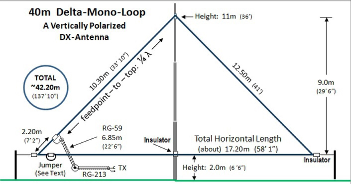
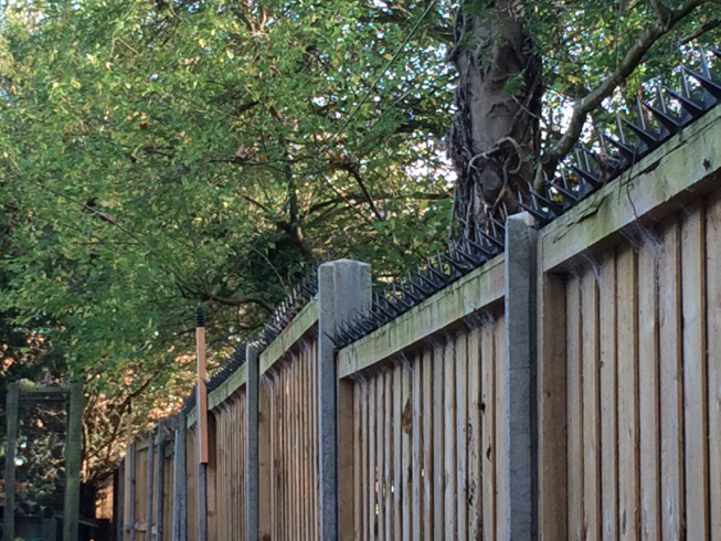
So instead of the pole I have a tree and I have run the bottom element along the top of the fence with some insulators to hold it about a foot above the top of the fence.
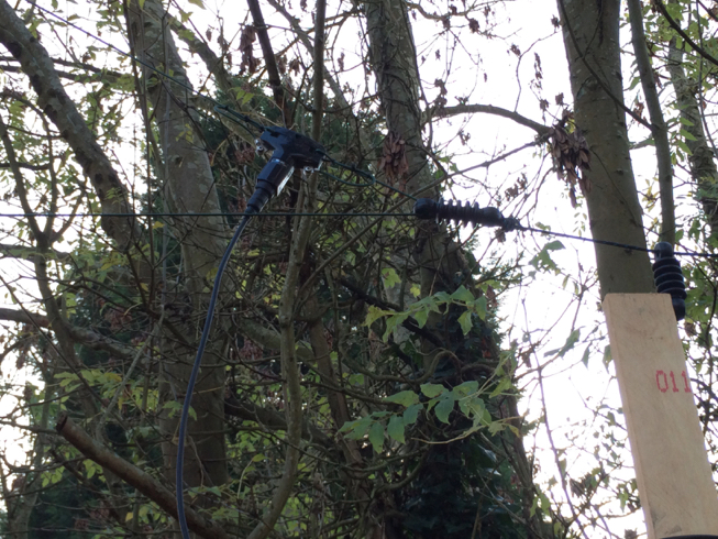
i had a spare balun from the dipole so used that. It is no heavier than an insulator really.
I took off about 1m to get it resonant where I wanted it and by playing with the geometry of the triangle the VSWR comes down to less than 1.5 over the band. Easily matched.
I gave it a go late last night and had 59’s into Europe and Russia with the furthest Algeria. So there is some potential and it is much less noisy than the dipole it replaced.
So if you have a fence with a tree in the middle this might work for you.
I found a plan for a 40m full wave loop which worked with my trees. This has an apex at the top as opposed to at the bottom. Like a pyramid I suppose.
So instead of the pole I have a tree and I have run the bottom element along the top of the fence with some insulators to hold it about a foot above the top of the fence.
i had a spare balun from the dipole so used that. It is no heavier than an insulator really.
I took off about 1m to get it resonant where I wanted it and by playing with the geometry of the triangle the VSWR comes down to less than 1.5 over the band. Easily matched.
I gave it a go late last night and had 59’s into Europe and Russia with the furthest Algeria. So there is some potential and it is much less noisy than the dipole it replaced.
So if you have a fence with a tree in the middle this might work for you.
call that an aerial
12/09/15 22:09
So we went out on the 70cms UKAC last Tuesday and Chris very kindly lent me his Diamond beam, which worked a treat. 70 QSO’s and some DX to Germany.
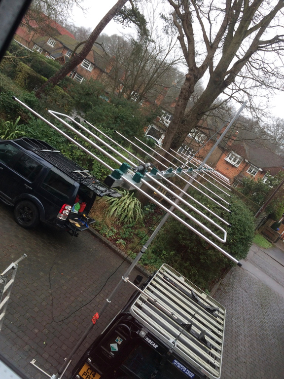
It was an interesting band, especially as there are not so many operators in IO91 so you have a better chance of getting further. So if I am going to carry on with these 70cms portable ops I am going to need my own antenna. And my weapon of choice is the Loop Fed Array LFA designs from Justin - the man behind Innov Antennas.
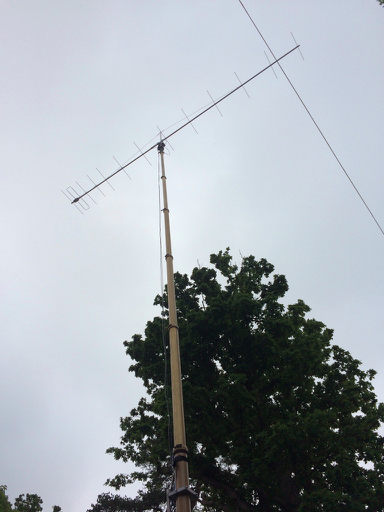
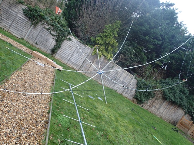
And here it is…….
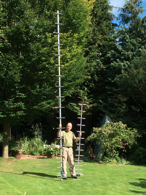
Some might say is might be getting slightly obsessive for a portable antenna or as Martin nicely put it.
“If you make it much bigger you won't need a radio just put your QSL card on the end and pass it to them”
It is 20 elements and you can see the spacing is quite a bit different when you compare it to the 15 element Diamond.
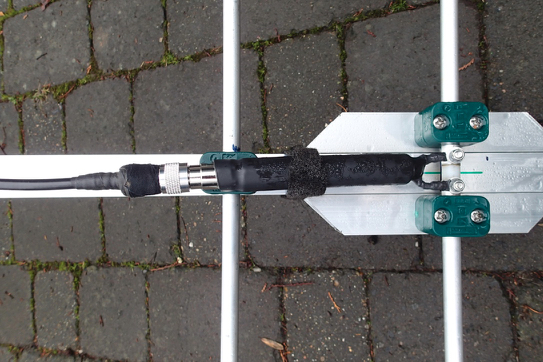
Construction follows the 2M and 6M ones earlier in the blog and below is a detail of the matching stub.
As I haven’t got a UHF analyser I don’t know how well it matches yet, so I suppose the proof will be on the next Tuesday I am up on the hill.
Give me a shout to try it out.
It was an interesting band, especially as there are not so many operators in IO91 so you have a better chance of getting further. So if I am going to carry on with these 70cms portable ops I am going to need my own antenna. And my weapon of choice is the Loop Fed Array LFA designs from Justin - the man behind Innov Antennas.
And here it is…….
Some might say is might be getting slightly obsessive for a portable antenna or as Martin nicely put it.
“If you make it much bigger you won't need a radio just put your QSL card on the end and pass it to them”
It is 20 elements and you can see the spacing is quite a bit different when you compare it to the 15 element Diamond.
Construction follows the 2M and 6M ones earlier in the blog and below is a detail of the matching stub.
As I haven’t got a UHF analyser I don’t know how well it matches yet, so I suppose the proof will be on the next Tuesday I am up on the hill.
Give me a shout to try it out.
Testing Testing
12/07/15 09:59
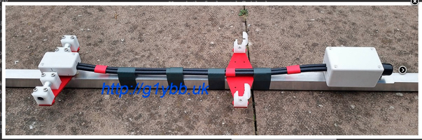
Ok so we have got the beam down again and the balun off
Chickens mind your heads!
Thats the balun which I have taken off and put the beam back up. And a check on the meter with the balun shows no resonance and a short.
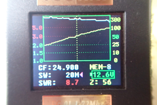
See the comparison without the balun below.
The fix was super simple. I thought I was going to have to take it all apart but it was just a strand of the centre core touching in the PL259 .
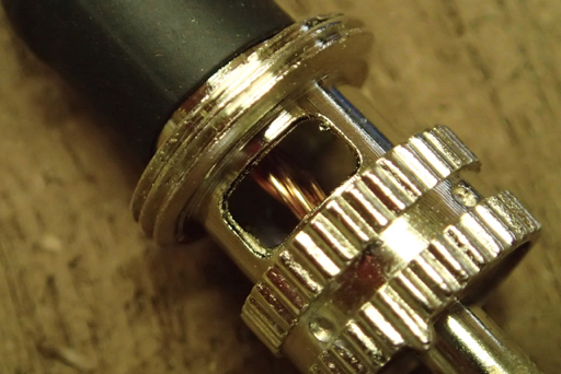
I have pushed it back and bingo we are in business. I will check again and it might be sensible to re do the connector but there is little movement in it as it is fixed to the centre post.
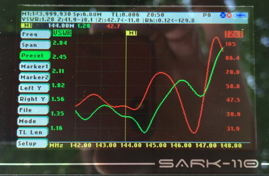
Here is the overall plot without the balun for these readings
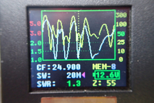
and if we look at the individual plots you will see they are spot on
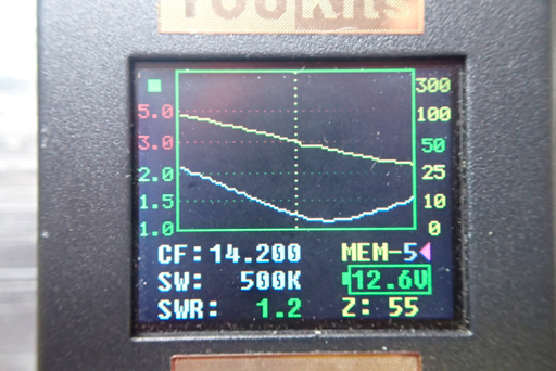
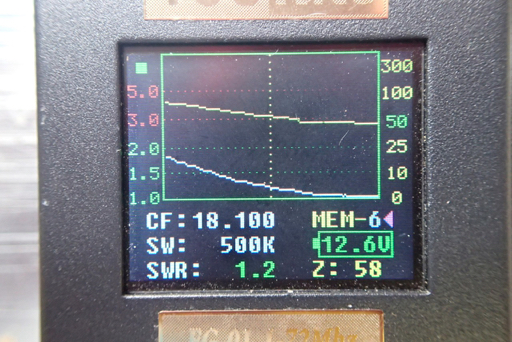
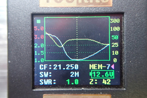
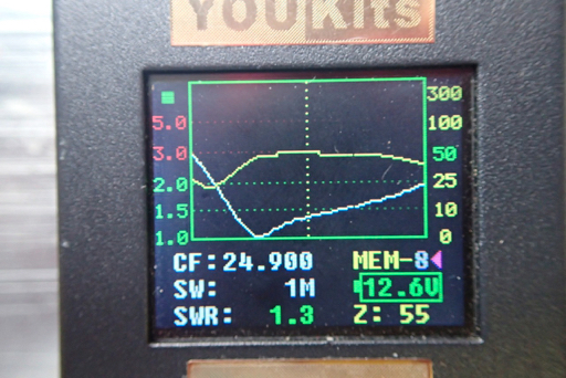
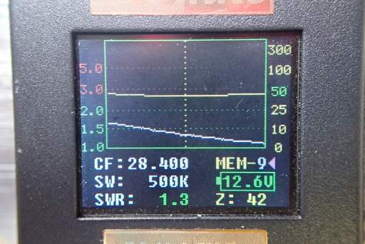
So there you are a quick fix and we are ready to take it down (again) and put the balun back on for a test. Although the impedance looks pretty fine to me without any help.
Chickens mind your heads!
Thats the balun which I have taken off and put the beam back up. And a check on the meter with the balun shows no resonance and a short.
See the comparison without the balun below.
The fix was super simple. I thought I was going to have to take it all apart but it was just a strand of the centre core touching in the PL259 .
I have pushed it back and bingo we are in business. I will check again and it might be sensible to re do the connector but there is little movement in it as it is fixed to the centre post.
Here is the overall plot without the balun for these readings
and if we look at the individual plots you will see they are spot on
So there you are a quick fix and we are ready to take it down (again) and put the balun back on for a test. Although the impedance looks pretty fine to me without any help.
It's Arrived
11/07/15 09:26
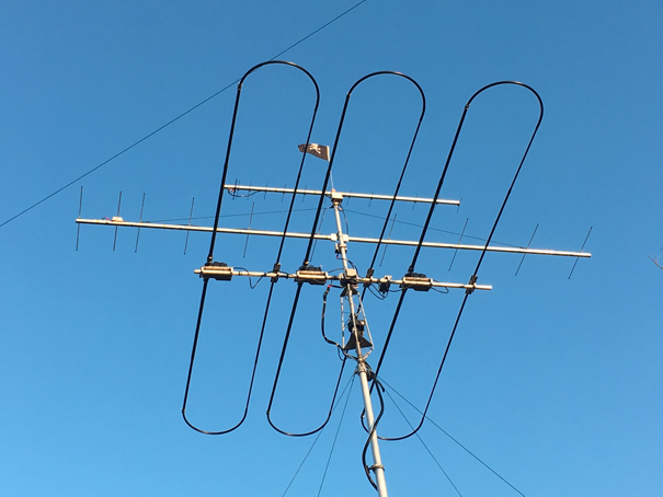
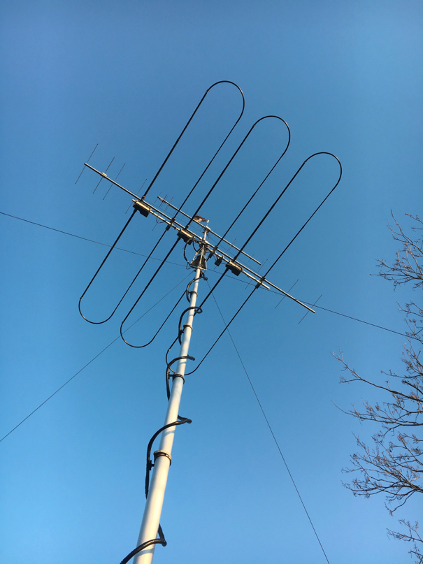
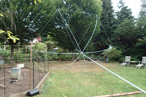
Oh yes.. we have all been waiting for the hex beam. And it is finally here.
I had intended to make this my home base antenna when I ordered it at the beginning of the year but could not bear the wait to get a better performing antenna than my trusty Gap Titan, which the neighbours said had to go, came down.
As you know I was forced into a planning application for a telescopic mast and with no Hex in sight went to Ron at Vinecom for a StepIr DB11. Which is brillinant. No doubt about that so I will say it again. It is BRILLIANT.
So question, if I can get any sort of comparison set up here, can we see how the Spidex hex beam performs using the DB11 as a comparison. Of course coastwise there is none. The hex is sub £500 and the DB11 tops £2.5k. (no telling Mrs LDZ now).
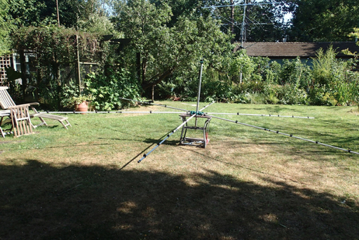
So here is what you get in Waldi’s hex. and if i remember correctly the one I have is the light version. It is eventually going to be put to use for field days and the mini dxpeditions.
Here are the contents. the fibreglass spreaders in three parts each, the centre hub and the centre post to school you connect the wire elements.
The first job, which gets done only once is to put the plastic hooks onto the spreaders and Waldi has done one of each for you to follow. So just use a marker and mark each tube, wine a bit of tape around it and put the clamp and “D:” ring on. This will take an hour or so. Make sure they are lined up on the one with 4. Otherwise this is straightforward. It all is really.
Right, you are back with me after having done that. Now here is the fun bit. Slotting everything together.
Sit the hub on a stand of some sort to stop it rolling about and put the post bit into it.
Then you are free to slot the spreaders (possibly not the right technical term) in. They are numbered but as far as I can see are all the same so I doubt if is would make any difference where they went.
One thing that you might want to do if you are going to be taking it apart a lot, like me, is to treat the aluminium to aluminium connections with some anti-seize.
Now simply take the lines already on the end of the spreaders and hook them onto the eyelet on the top of the centre post.
With that done, and it takes seconds to do the whole thing, you are ready to thread the wires.
Now this is where I am going to work on making this easier for the portable work. With the design as it is you have to thread each element through each D ring. What would be good would be to be able to clip to the d ring as you go round thus not having to feed the whole element through each ring. I will let you know who that idea works out.
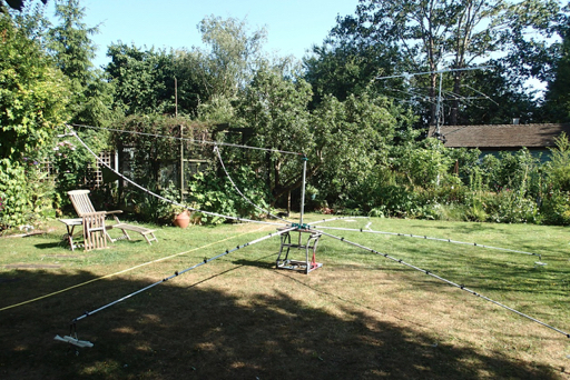
That is the 6m element on. Basically like a folded Moxon. You cants see the orange bits which is where the driven and reflector are separated.
Thats the connection to the centre post. Again to make it easy in the field I will swap the just for wing nuts.
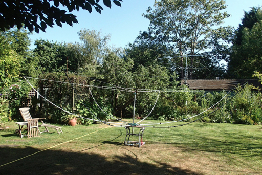
And that’s as far as we have got before having to go out. All in all a couple of hours and its done.
It is bigger than the DB11, which surprises me but much lighter.
I have the Spidex aluminium pole as well so we will be diving that a whirl and trying to get the thing up in the garden to evaluate it soon. Check back and see as we will cover a quick test as well as taking it apart and any modifications for quicker field assembly.
I had intended to make this my home base antenna when I ordered it at the beginning of the year but could not bear the wait to get a better performing antenna than my trusty Gap Titan, which the neighbours said had to go, came down.
As you know I was forced into a planning application for a telescopic mast and with no Hex in sight went to Ron at Vinecom for a StepIr DB11. Which is brillinant. No doubt about that so I will say it again. It is BRILLIANT.
So question, if I can get any sort of comparison set up here, can we see how the Spidex hex beam performs using the DB11 as a comparison. Of course coastwise there is none. The hex is sub £500 and the DB11 tops £2.5k. (no telling Mrs LDZ now).
So here is what you get in Waldi’s hex. and if i remember correctly the one I have is the light version. It is eventually going to be put to use for field days and the mini dxpeditions.
Here are the contents. the fibreglass spreaders in three parts each, the centre hub and the centre post to school you connect the wire elements.
The first job, which gets done only once is to put the plastic hooks onto the spreaders and Waldi has done one of each for you to follow. So just use a marker and mark each tube, wine a bit of tape around it and put the clamp and “D:” ring on. This will take an hour or so. Make sure they are lined up on the one with 4. Otherwise this is straightforward. It all is really.
Right, you are back with me after having done that. Now here is the fun bit. Slotting everything together.
Sit the hub on a stand of some sort to stop it rolling about and put the post bit into it.
Then you are free to slot the spreaders (possibly not the right technical term) in. They are numbered but as far as I can see are all the same so I doubt if is would make any difference where they went.
One thing that you might want to do if you are going to be taking it apart a lot, like me, is to treat the aluminium to aluminium connections with some anti-seize.
Now simply take the lines already on the end of the spreaders and hook them onto the eyelet on the top of the centre post.
With that done, and it takes seconds to do the whole thing, you are ready to thread the wires.
Now this is where I am going to work on making this easier for the portable work. With the design as it is you have to thread each element through each D ring. What would be good would be to be able to clip to the d ring as you go round thus not having to feed the whole element through each ring. I will let you know who that idea works out.
That is the 6m element on. Basically like a folded Moxon. You cants see the orange bits which is where the driven and reflector are separated.
Thats the connection to the centre post. Again to make it easy in the field I will swap the just for wing nuts.
And that’s as far as we have got before having to go out. All in all a couple of hours and its done.
It is bigger than the DB11, which surprises me but much lighter.
I have the Spidex aluminium pole as well so we will be diving that a whirl and trying to get the thing up in the garden to evaluate it soon. Check back and see as we will cover a quick test as well as taking it apart and any modifications for quicker field assembly.
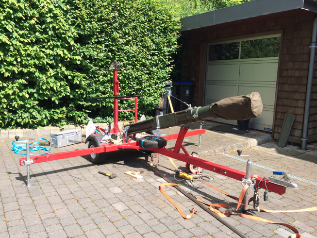
Fitting the Mast
03/06/15 08:07
After the seals were done on the club mast I brought it home to scratch mu head about fitting it to the trailer.
It seems that there are a number of different variants of the Scam mast and our looks different to the one that G1NGE had in his photos.
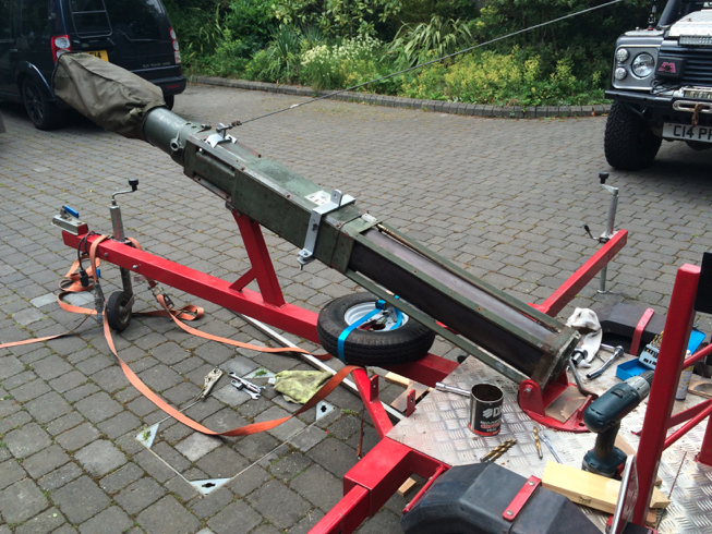
The question was how do you manhandle the massively heavy mast into the exact position that you need and after one failed attempt I resorted to good old ratchet straps and wedges.
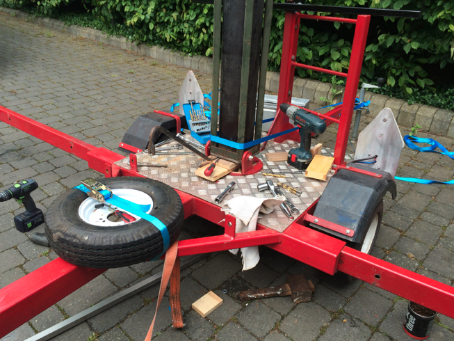
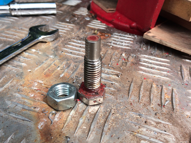
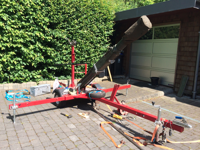
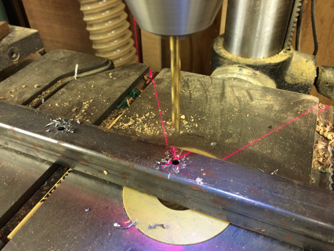
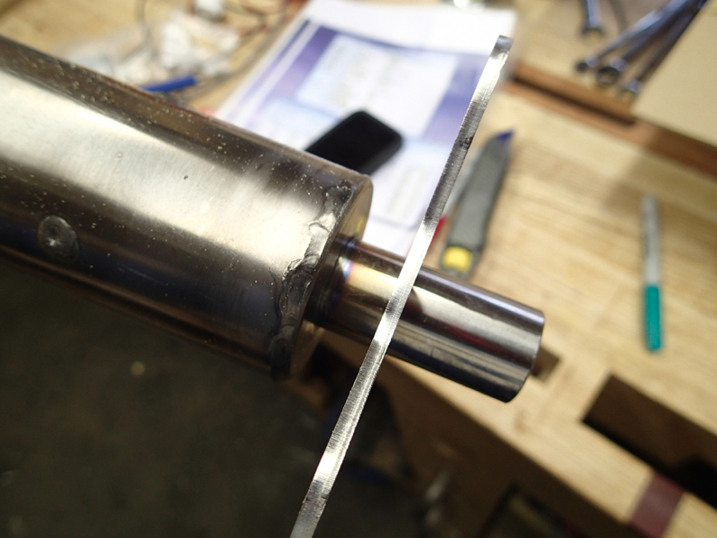
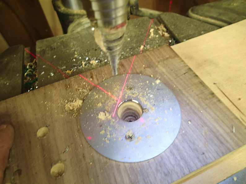
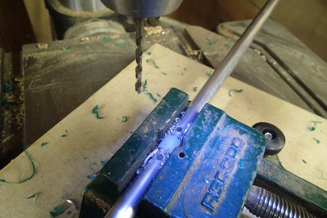
Then i turned down the bolts so that they would go into two holes drilled into the frame to pivot the mast. I used a centre drill to centre the hole in the threaded section to avoid damaging the threads and then opened it up to 9.5mm
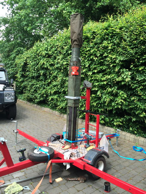
i thought it important to set the mast vertical before drilling the holes seeing as that is where we want it to end up
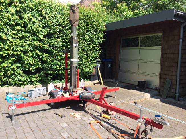
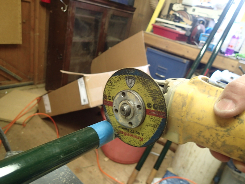
The rest just involved grinding the backets to get them to fit
Here it is done. Just needing some painting and the cover plates fitting.
It seems that there are a number of different variants of the Scam mast and our looks different to the one that G1NGE had in his photos.
The question was how do you manhandle the massively heavy mast into the exact position that you need and after one failed attempt I resorted to good old ratchet straps and wedges.
Then i turned down the bolts so that they would go into two holes drilled into the frame to pivot the mast. I used a centre drill to centre the hole in the threaded section to avoid damaging the threads and then opened it up to 9.5mm
i thought it important to set the mast vertical before drilling the holes seeing as that is where we want it to end up
The rest just involved grinding the backets to get them to fit
Here it is done. Just needing some painting and the cover plates fitting.
Mast For VHF
17/05/15 19:32
Well whilst I am still waiting for the mast that is coming with the HexBeam from Poland I need to get something ready for the summer. I just can’t wait any longer.
So I have pushed the Moonraker 15M masts into operation.
You can get a guy kit from Nevada which, although designed for Spider poles works equally as well with the Moonraker one.
I tried it with two sets of guys and it was fine until it came to trying to lift the antenna on it. The problem is that the mast sections are 2.5m long so you have to be up a ladder, or on top of a car to push them up and you have to have something stabilising the bottom section.
I added a third aluminium guy section, without the bearing, on the bottom section and that solved the issue.

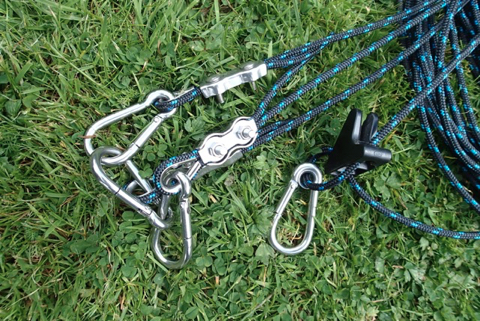
I made up the guys with the same braid i used for the home mast and added the neat stainless steel connections to the ends.
I tried lifting it with just the two guys but no go.
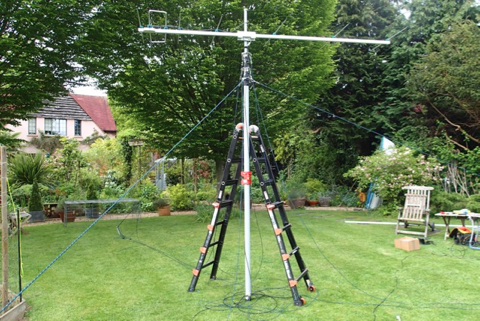
So a third on the bottom section stabilised it all. Pity you have to have ladders to get to the top though.
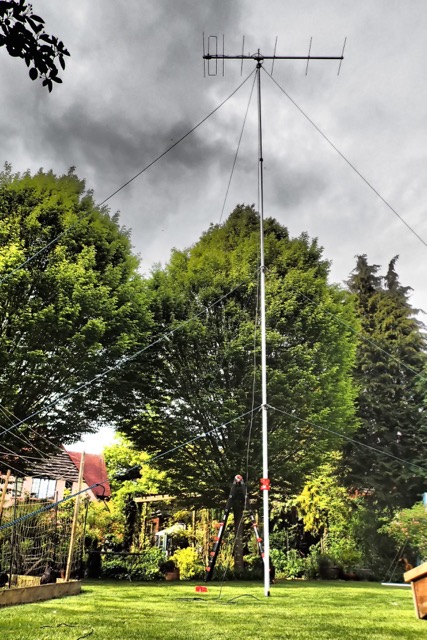
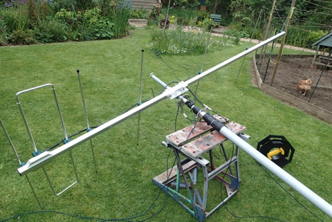
Here are some shots of it up at about 10M. It did oscillate a bit in the wind but I had a couple of QSO’s on 2W on the KX3 which proved that it works.
So I have pushed the Moonraker 15M masts into operation.
You can get a guy kit from Nevada which, although designed for Spider poles works equally as well with the Moonraker one.
I tried it with two sets of guys and it was fine until it came to trying to lift the antenna on it. The problem is that the mast sections are 2.5m long so you have to be up a ladder, or on top of a car to push them up and you have to have something stabilising the bottom section.
I added a third aluminium guy section, without the bearing, on the bottom section and that solved the issue.
I made up the guys with the same braid i used for the home mast and added the neat stainless steel connections to the ends.
I tried lifting it with just the two guys but no go.
So a third on the bottom section stabilised it all. Pity you have to have ladders to get to the top though.
Here are some shots of it up at about 10M. It did oscillate a bit in the wind but I had a couple of QSO’s on 2W on the KX3 which proved that it works.
2M Yagi for Portable Use
03/05/15 18:52
I was intending to use the 9 element for portable use but that is now stuck up on the mast so I decided to make another one.
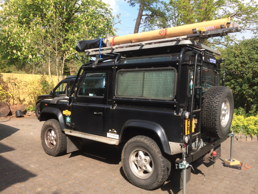
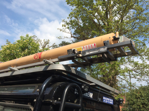
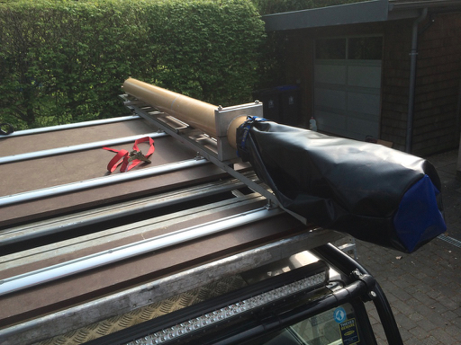
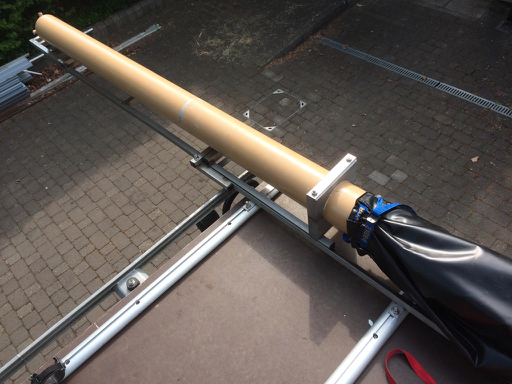
This time a 7 element which is about 3m long so it can go on the roof rack in one piece with the elements folded in. No need for joiners.
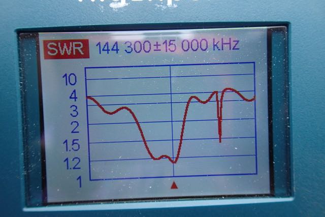
It is to G0KSC’s plans again and comes out of the box at 1:1.3 on 144.300 at the shed testing level facility.
I am still waiting for the hex beam and mast to arrive. When it does this will go on top and we will pop over to wales with the go box for a test.
This time a 7 element which is about 3m long so it can go on the roof rack in one piece with the elements folded in. No need for joiners.
It is to G0KSC’s plans again and comes out of the box at 1:1.3 on 144.300 at the shed testing level facility.
I am still waiting for the hex beam and mast to arrive. When it does this will go on top and we will pop over to wales with the go box for a test.
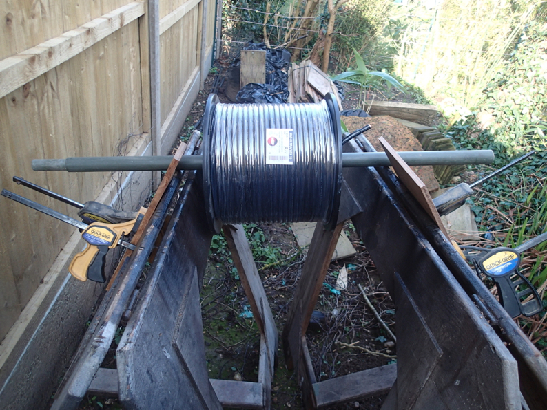
Cable trunking
15/04/15 12:52
Here are some picures of the galvanised trunking that take the cables around the workshop to the mast
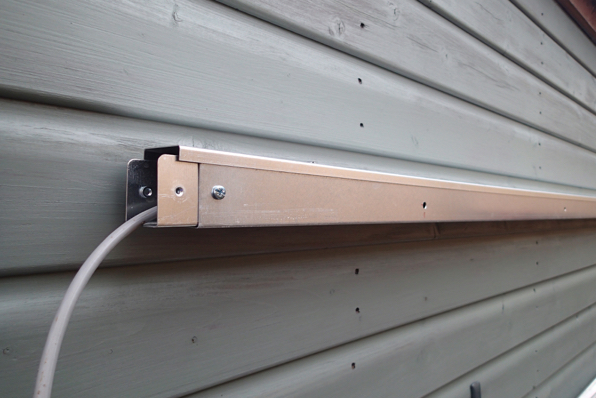
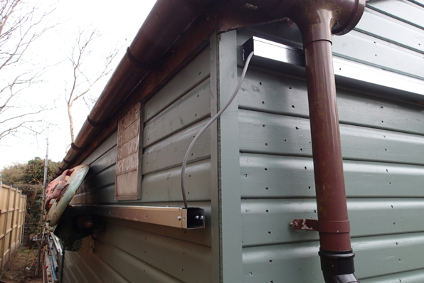
and here is the box to stop the mice coming in
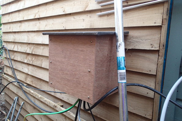
and here is the box to stop the mice coming in
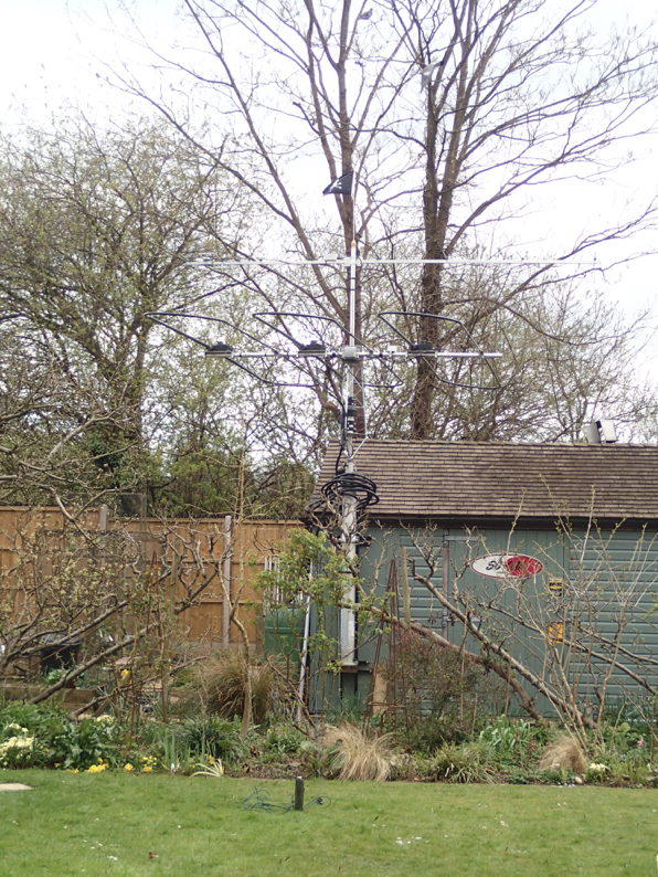
It's Up
13/04/15 19:41
Dem tree fellas came round today and gave the ash trees a short back and sides so the mast could finally be raised to test the Stepir.
isn’t she a beauty.
The antenna can be tuned for each band and all were pretty much spot on and the only high SWR was on 6M.
To say it is chalk and cheese with the vertical is an understatement. But thats what you expect with this much technology. So how did it perform. Well I had a couple of hours on the 5000 and had qso’s with, Japan, South Africa, USA, India
57 into Japan with 50w can’t be bad.
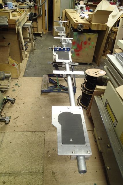
Its up ....as far as it will go
12/04/15 19:40
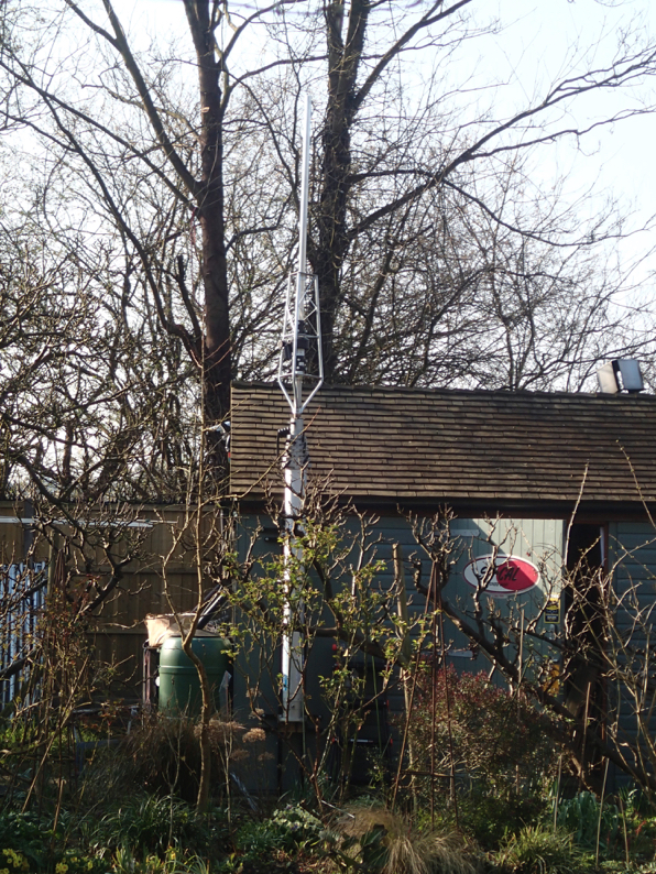
The stepir is up.
Well on the mast. It needs the trees to be trimmed to go all the way up and as it was windy today I stuck with it at shed level.
To get us there first job was to test the motors and the wiring. You can run a setup programme and check they go in and out as they should.
Then the fibreglass arms need extending and fixing in place with adhesive filled heat shrink
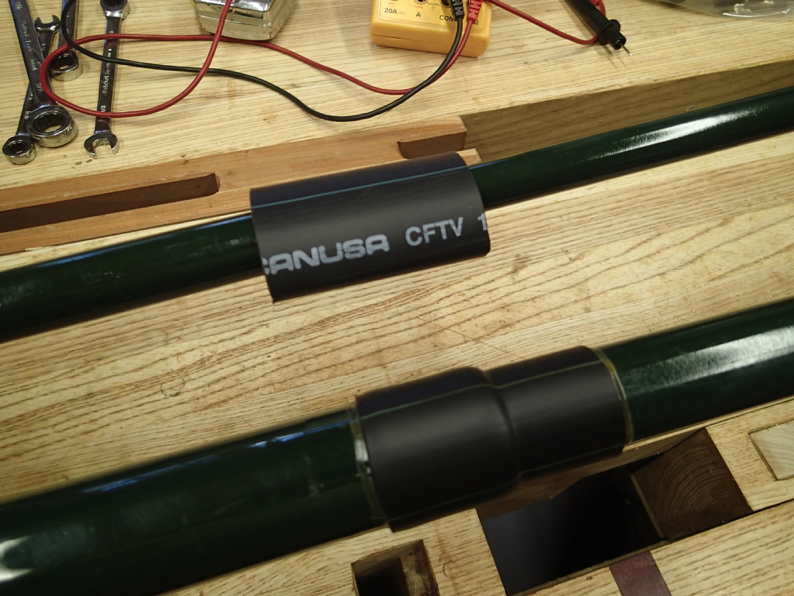
Tubes are then shortened to the right length and prepared for the standing on the roof fixing technique that will ha[[en later
With 26kg of it . (the stepir not Martin) on the mast we tested that went up and down. (down jerkily)
Then wrapped the cables in spiral wrap. What a long job that was. But worth it.
Couldn’t have done it all on my own.
It was getting cold so we called it a day.
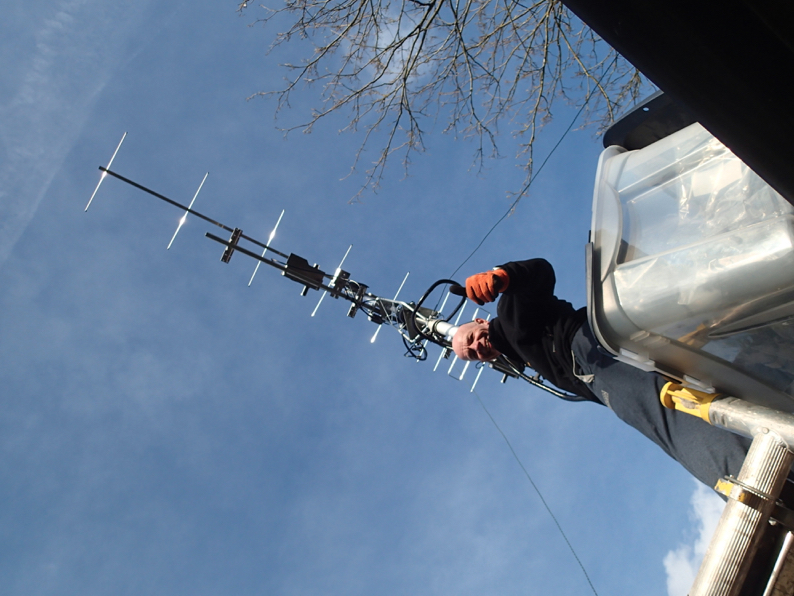
Today i got the trombones on. There was a lot of fiddling on the roof so no photos,, Just the majesty of the thing now it is up.
It works pretty well at roof level as well.
See it blends in a treat.
Well on the mast. It needs the trees to be trimmed to go all the way up and as it was windy today I stuck with it at shed level.
To get us there first job was to test the motors and the wiring. You can run a setup programme and check they go in and out as they should.
Then the fibreglass arms need extending and fixing in place with adhesive filled heat shrink
Tubes are then shortened to the right length and prepared for the standing on the roof fixing technique that will ha[[en later
With 26kg of it . (the stepir not Martin) on the mast we tested that went up and down. (down jerkily)
Then wrapped the cables in spiral wrap. What a long job that was. But worth it.
Couldn’t have done it all on my own.
It was getting cold so we called it a day.
Today i got the trombones on. There was a lot of fiddling on the roof so no photos,, Just the majesty of the thing now it is up.
It works pretty well at roof level as well.
See it blends in a treat.
2M Beam is up (and down)
07/04/15 08:55
Sorry I missed out on the Fox Hunt. A combination of feeding the bees, doing some home stuff and showing my face kept me home. Which also gave me change to put the scaffold up and plonk the 2m beam onto the rotator.
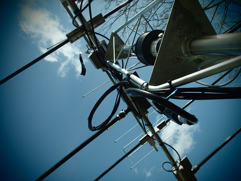
there is more fiddling to do but it is up, and a quick test shows that the beam works. The proof will be in seeing what we can do in the comp tonight.
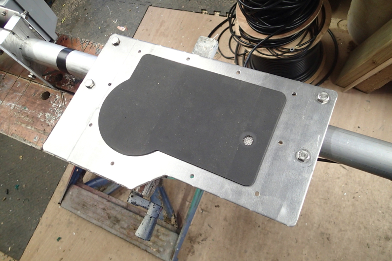
Above is the top that takes the skull and crossbones.
Below …yes it clears the trees just. not sure the Stepir will though.
there is more fiddling to do but it is up, and a quick test shows that the beam works. The proof will be in seeing what we can do in the comp tonight.
Above is the top that takes the skull and crossbones.
Below …yes it clears the trees just. not sure the Stepir will though.
Rotator Cage Ahoy
05/04/15 19:11
Back from Uri’s, unloaded and up the ladder for a fettle of the mast.
I let each section up cleaned it and gave it a quick grease. Not satisfied to leave it at that I bolted the rotator cage on and put in the short stub mast. This is lighter gauge that the ali scaffold pole and I think will still give sufficient separation from the HF beam to the 2M, whilst keeping the weight down.
In the Down position Mrs LDZ says it “looks quite smart”. I haven’t ventured asking her what she thinks about it when it is up. That it yet to come!
Oh ….it’s bigger that the vertical that was the cause of it all.
But it does go up and down. Which is great fun.
Tomorrow we need to get the 2m beam on to it for the comp on Tuesday. Hope you are all going to join in.
Saturday Morning Erection
05/04/15 18:48
Ever had the urge to leap out of bed on a Saturday and get it up?……Yes. Thought so. Must be something in common with radio amateurs.
So before loading up the trailer for the DX Picnic Greg, my pal from across the road came over and together we managed to get the 50kg mast onto its framework. and after a quick adaptation of the compressor it was on its way up.
there is one particularly sticky section which I will need to look at but it goes up fine and straight. To let it down there is a valve on the side that lets a regulated amount of air out for a gradual decent.
Didn't quite get it up
03/04/15 19:15
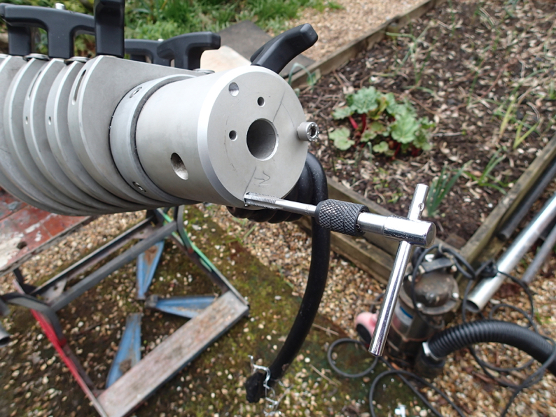
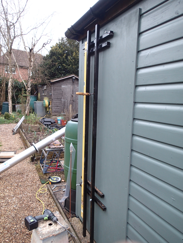
Today was a full on construction day. I needed to make the stand off backed to clear the gutter and sort out the mast head fixing.
Luckily I had some square section steel from the roadster build in the shed so that got pressed into action for the framework for mounting the mast plates. I mocked it up and them sat the mast on it before tack welding it.
Then i welded it up and gave it a spray with hammerite.
Whilst that was drying I turned to the top mount. As these masts seem to be used for cameras the heads have an interchangeable spigot arrangement that didn’t look too got for what i want to put on top of it.
So I added some plates onto the stub which goes (with much swearing) into the rotator cage.
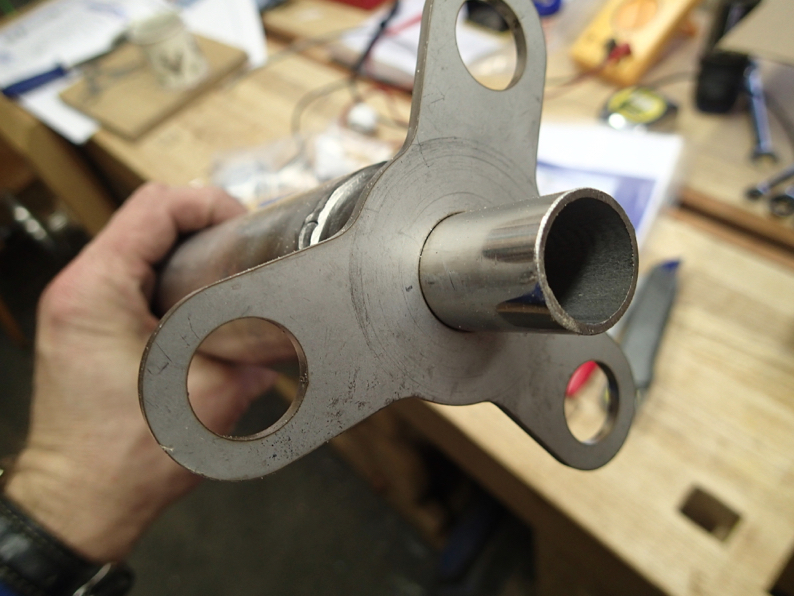
I then drilled out some holes so i could bolt it onto the mast head
Here it is mocked up
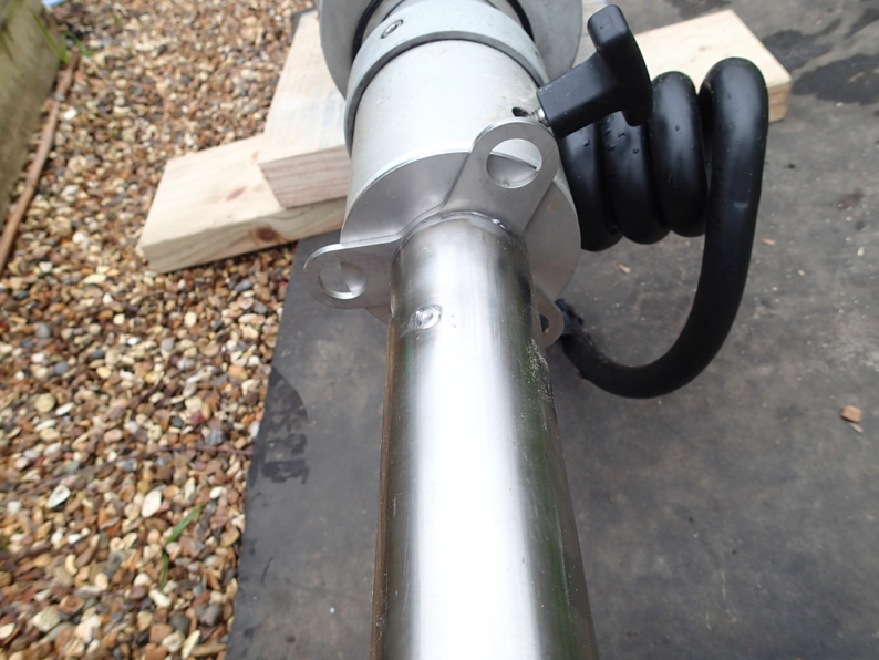
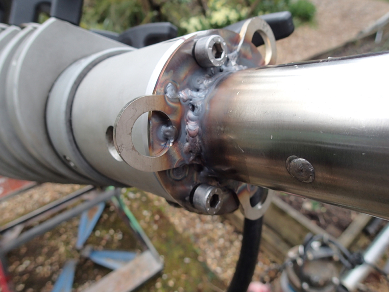
Then a tricky bit of welding the plates onto the stub and tapping threads for some M8 bolts into the head
Not the neatest welding I know but only birds are going to look at it. Thats the problem with spot welding in an attempt to keep everything flat
Then a call to Mrs LDZ for a helping hand to bolt it all to the shed with ply spreader plates to both sides and the load being taken onto the concrete slab
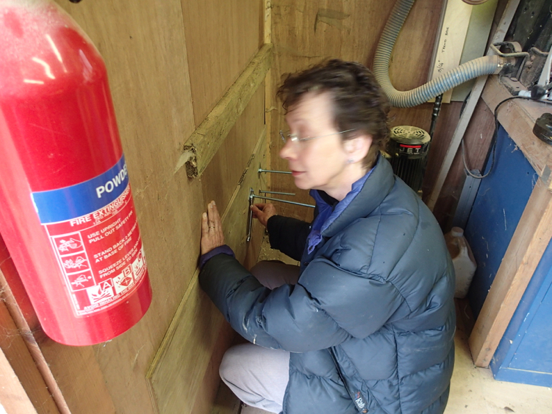
Thats as far as we got with mounting it as both of us (Mrs LDZ with her titanium back operation) couldn’t lift it into place.
So whilst I pondered on that problem I spent an hour swearing at the stub again as it is not the size of a scaffold pole, which all the rotator cages are made for, it is 50.8mm . As opposed to 48.8.
So a big hammer and a clamp eventually sorted it .
So that’s all for today folks. Hopefully I will come up with a cunning plan for getting the mast on the bracket involving scaffolding in my very odd dreams.
See you at the DX Picknic providing we are not flooded out.
CC
Luckily I had some square section steel from the roadster build in the shed so that got pressed into action for the framework for mounting the mast plates. I mocked it up and them sat the mast on it before tack welding it.
Then i welded it up and gave it a spray with hammerite.
Whilst that was drying I turned to the top mount. As these masts seem to be used for cameras the heads have an interchangeable spigot arrangement that didn’t look too got for what i want to put on top of it.
So I added some plates onto the stub which goes (with much swearing) into the rotator cage.
I then drilled out some holes so i could bolt it onto the mast head
Here it is mocked up
Then a tricky bit of welding the plates onto the stub and tapping threads for some M8 bolts into the head
Not the neatest welding I know but only birds are going to look at it. Thats the problem with spot welding in an attempt to keep everything flat
Then a call to Mrs LDZ for a helping hand to bolt it all to the shed with ply spreader plates to both sides and the load being taken onto the concrete slab
Thats as far as we got with mounting it as both of us (Mrs LDZ with her titanium back operation) couldn’t lift it into place.
So whilst I pondered on that problem I spent an hour swearing at the stub again as it is not the size of a scaffold pole, which all the rotator cages are made for, it is 50.8mm . As opposed to 48.8.
So a big hammer and a clamp eventually sorted it .
So that’s all for today folks. Hopefully I will come up with a cunning plan for getting the mast on the bracket involving scaffolding in my very odd dreams.
See you at the DX Picknic providing we are not flooded out.
CC
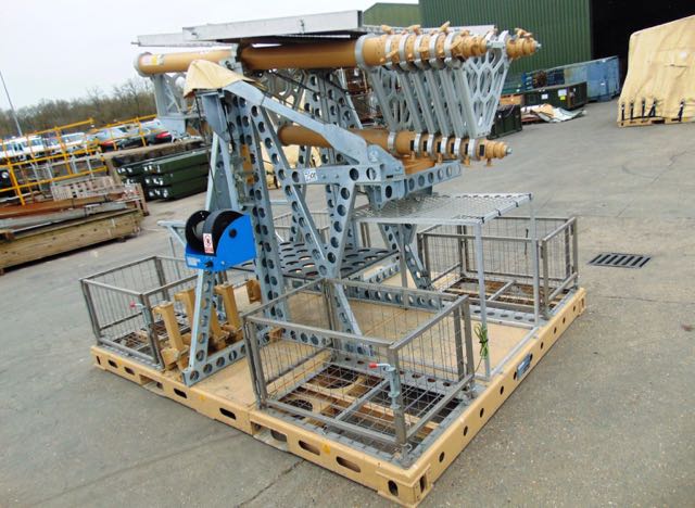
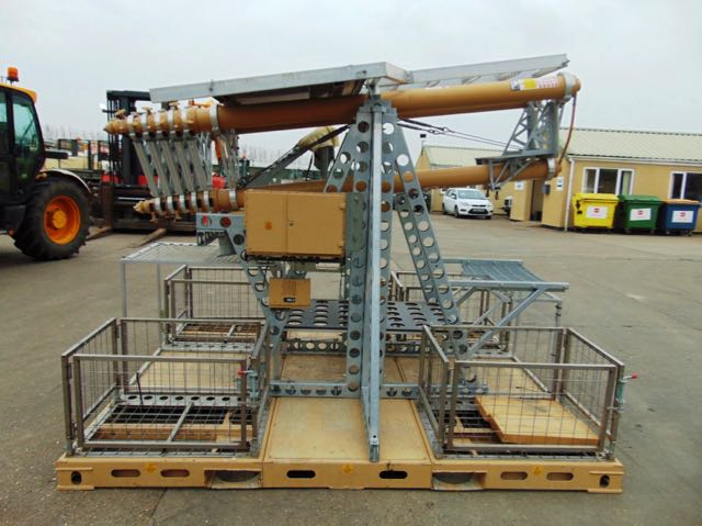
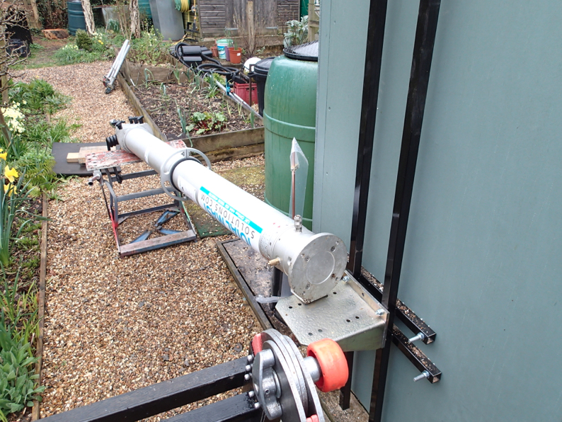
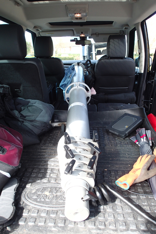
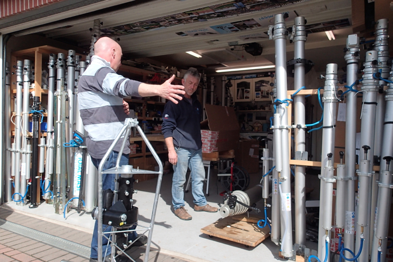
Mast Ahoy
02/04/15 20:46
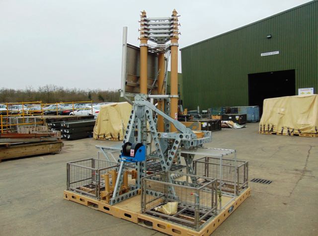
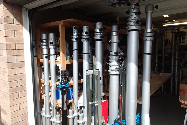
So the rest of the day was spent traveling to Total Mast Solutions in Loughborough to collect the mast.
Simon has loads of interesting still there and this one is nice chunky example.
So we loaded it up and when we got back had a quick pump up to see it inaction. You will have to wait for that.
There are some jobs to be done first, The stand off brackets that were supposed to clear the gutter don’t. so I need to make up some sort of spreader system.. And the top the fitment for the rotator cage, which is made to fit standard scaffold tube which is 48.8mm needs to adjusted some how to suit the 50mm dia stub.
So a trip to B&Q in the morning for some bits and then on with the installation. Enjoy the photos.
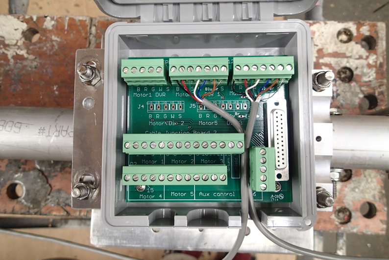
Progress on the StepIr
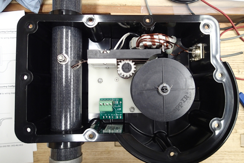
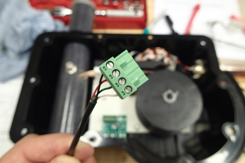
02/04/15 20:43
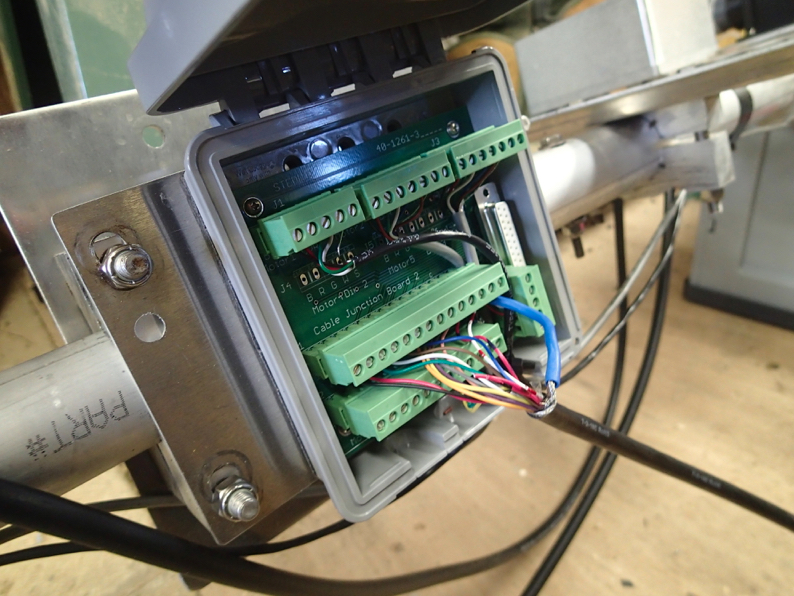
Before Martin came over I wired up the driven steppe motor and the relay box that controls whether the antenna is looking forward , backwards or both ways
Db11 a bit more
01/04/15 07:56
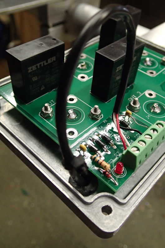
I managed to get a bit done on the Db-11 last night wiring up and fitting two of the EHU's .
Permission for Transmission 2
31/03/15 11:13
The permission has come through today. No nasty surprises with the conditions.
I agreed for the permission to be personal to me so that when we move, or Mrs LDZ does away with me, the mast comes down.
So fingers crossed for getting it up at the weekend !
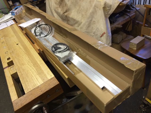
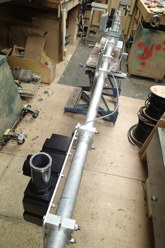
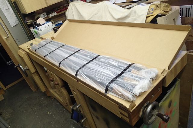
StepIR Build Day One
30/03/15 18:08
I had a great time with Ron at VineCom and collected the DB11 on Saturday
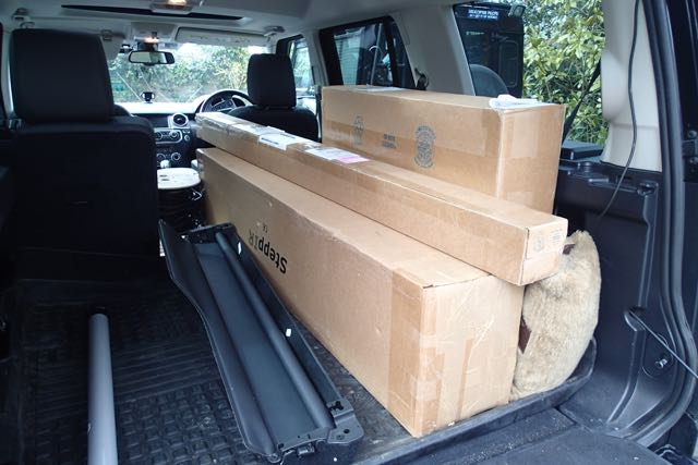
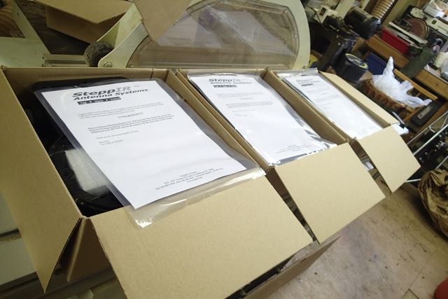
There is a fair bit to it. 3 boxes which Just fitted in the car with all the other stuff from the weekend away.
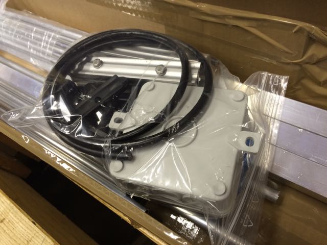
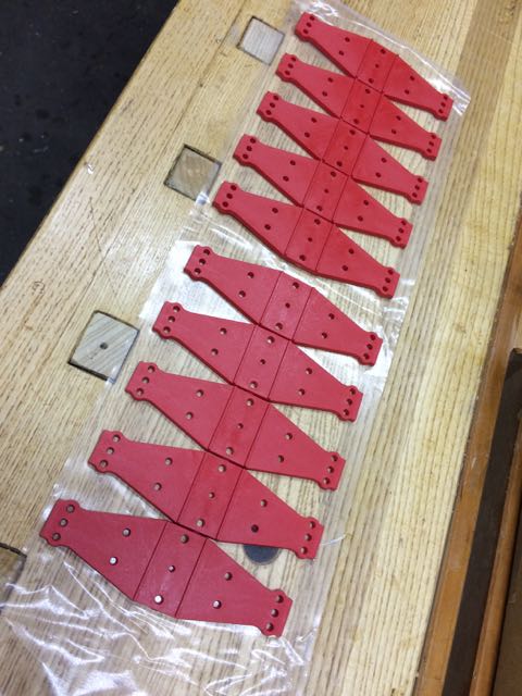
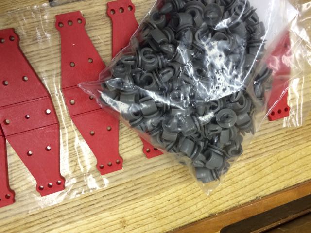
First day when we got back was spent checking the contents and setting up all the hardware on the boom. These are the fibreglass tube elements
The sweeps
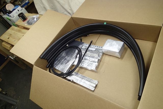
The three stepper motors
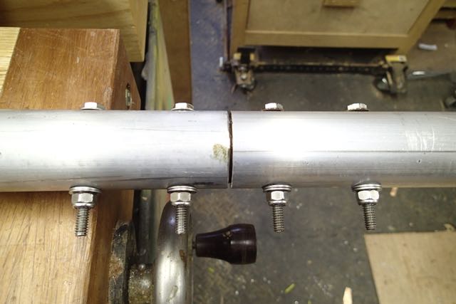
First job was the boom assembly and making sure everything is lined up and level
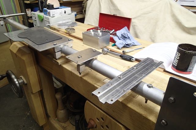
Next step will be to wire the motor units and the coax switch
But that’s for another day. How exciting.
There is a fair bit to it. 3 boxes which Just fitted in the car with all the other stuff from the weekend away.
First day when we got back was spent checking the contents and setting up all the hardware on the boom. These are the fibreglass tube elements
The sweeps
The three stepper motors
First job was the boom assembly and making sure everything is lined up and level
Next step will be to wire the motor units and the coax switch
But that’s for another day. How exciting.
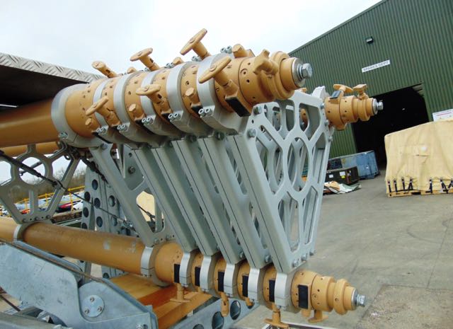
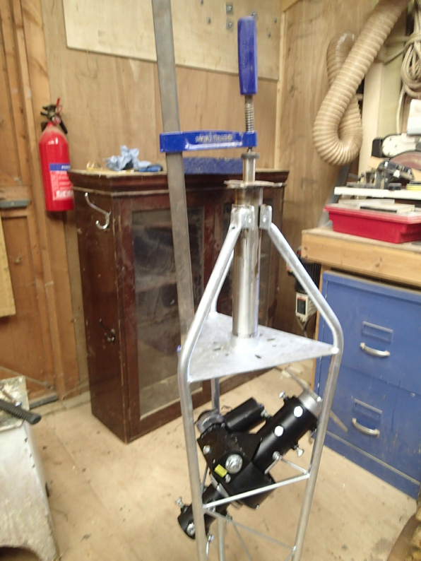
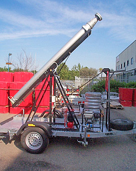
Mast Delays ??
27/03/15 08:25
Just had a mail from Total Mast Solutions who I am getting the pneumatic mast from. It is an ex demo one and was supposed to be out of the demonstration van for 23rd March but there are some delays, which I don’t quite understand. Lets hope its not stuck in there !
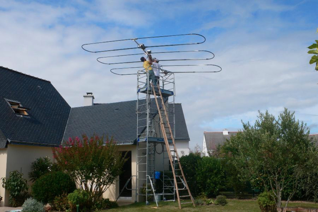
I had planned a day off to collect on Monday and for the interested Club members to help me swaying about on the scaffolding over the Bank Holiday.
Whether that happens or not we shall have to wait and see.
I like this picture. Very Thunderbirds….
I had planned a day off to collect on Monday and for the interested Club members to help me swaying about on the scaffolding over the Bank Holiday.
Whether that happens or not we shall have to wait and see.
I like this picture. Very Thunderbirds….
Looking forward to the weekend
25/03/15 16:20
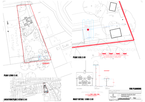
Permission For Transmission
25/03/15 15:52
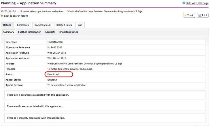
This has just been posted on the Council website.
The actual details and conditions will tell the story
Comments Now Possible
21/03/15 08:28
Iv’e updated the site to that comments are possible as are subscriptions via RSS.
So if you want to subscribe to the posts or discuss anything it should be possible. Let me know if any of it doesn’t work as this is a bit like the blind leading the blind here!
Keep an eye out for next week when we are off to Oswestry to collect the StepIR and then Leicester for the pneumatic mast.
What fun…
Getting it up at the weekend
09/03/15 08:00
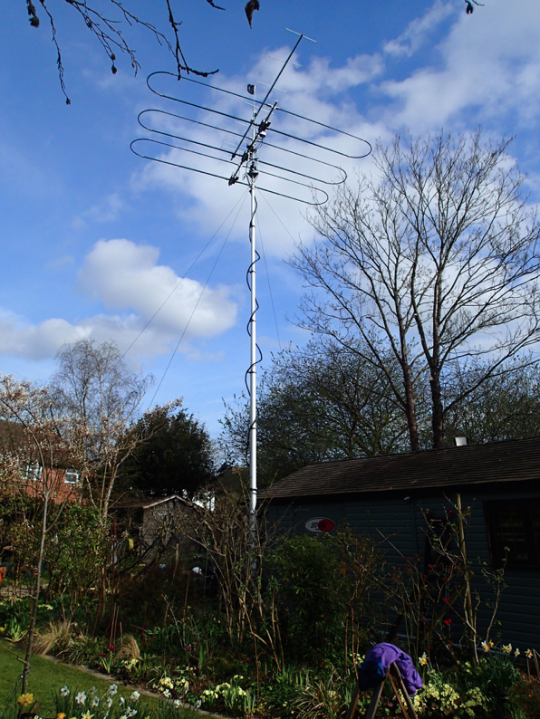
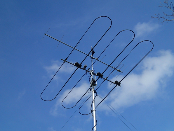
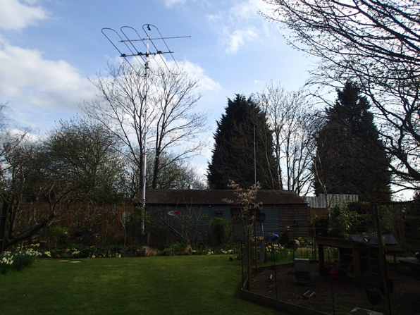
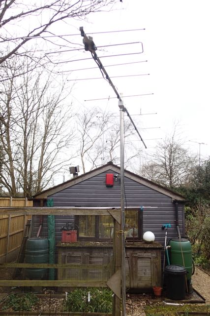
Putting up the 2M beam over at 2EØSUR’s QTH
In moving the site to the DropBox some of the pictures and text have gone AWOL. I will track them down and re post.
In moving the site to the DropBox some of the pictures and text have gone AWOL. I will track them down and re post.
Yagi Build
03/03/15 13:26
To get ready for the 2M competitions I got together with Martin to make up a couple of 9 element Yagi's to Justin, GØKSC's plans.
You will find details on his website
We also sells ready built antennas for those not wanting to make them up. Innovantennas
So how did we go about it:
First off you have to decide what you are going to build. We went for a loop fed yagi with a nice 14dBi gain and a 4.5m boom. All the dimensions are on the website as are the suggested tube dimensions. You need to decide on what boom you are going to use and go and order the aluminium.
We went to Aluminium Warehouse via the internet. There is a carriage charge so if you are going to make a few aerials then it pays to buy all you need in one go. You also need to order the insulators from Justin to match the tube size that you have ordered.
When it comes you will need some tools. All pretty basic, saw, rule and the usual soldering stuff we all have. It pays to have a couple of more specialist tools such as a rivnut (or captive nut) installation tool a, pipe cutter and a tube bender. You can get away without these by buying the loop ends from Justin and fixing the insulators with self tappers.
All set? Then off we go.
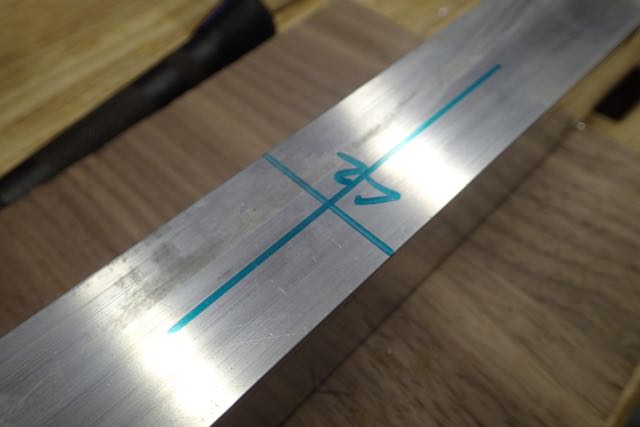
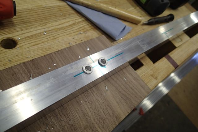
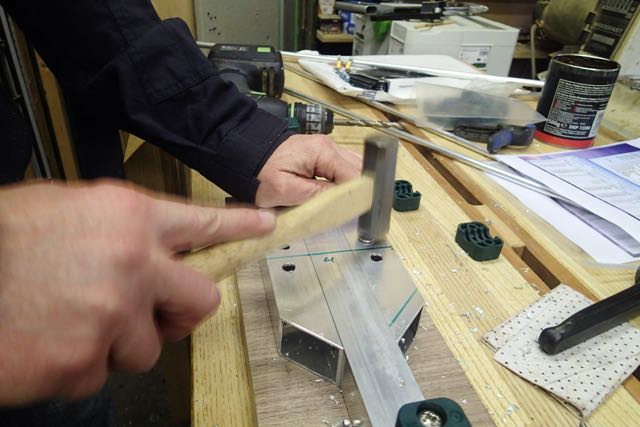
1 Setting Out
All projects start with reading and understanding the plans and measuring everything out twice before committing to drilling holes.
Mark the actual positions of the elements down the boom and mark the centre lines for the fixings. This one is marked L2 or the 2nd loop element.
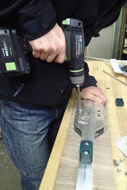
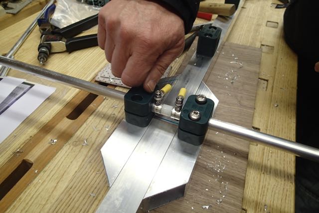
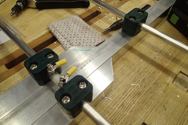
2 Riv nut fixing
I like the idea of riv nuts as you can take the elements off for transport and still have a secure fixing. Yes....we are using these for portable operation.
So look at the insulator and line up the bit where the element goes with the line you have marked. The line is NOT where the hole goes. It is where the element goes.
Some insulators have two holes and some one. Make sure you have the right ones. On ours the doubles were for the fed loop and singles for the elements.
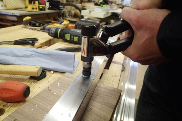
You will need to open up the bottom hole in the insulator so it sits flush on the boom over the riv nut
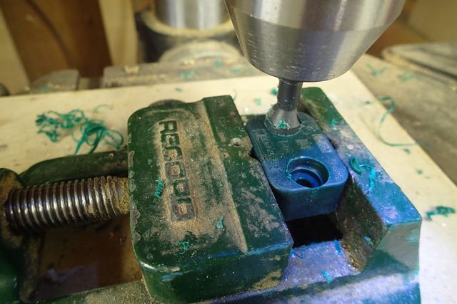
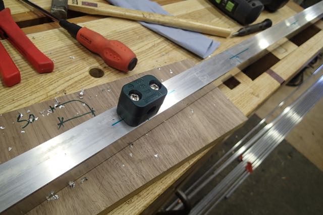
This is what we are aiming for and below is how we get there in more detail.
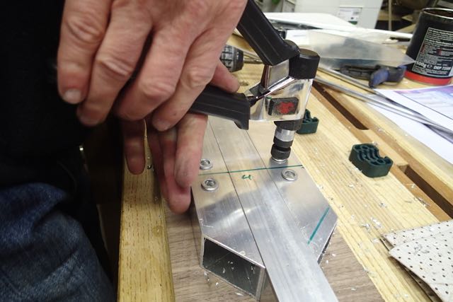
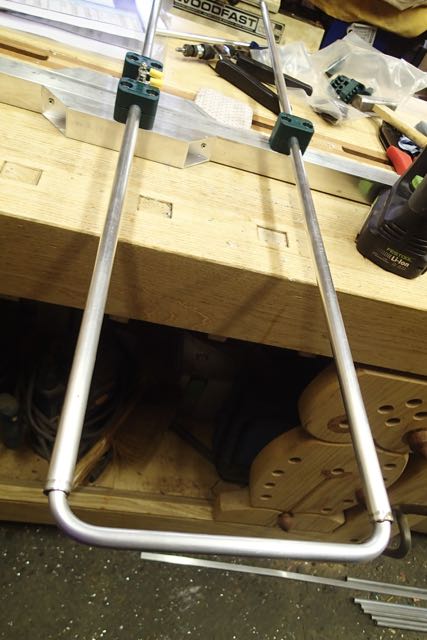
3 Driven Element Fixing
The driven element is like a dipole and has an insulator between a split tube. The supports will be off each side of the boom so we need to widen it at the driven element.
You will have some of the boom left over which you can chop into two bits and then angle the ends at 45 degrees.
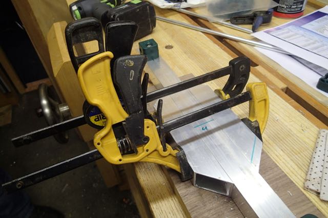
Then pop rivet these on where the 45 degree bit is cut
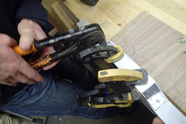
Then set out the insulators again and drill holes for them
4 Driven Element
You should have also brought Justin's insulator for the driven element to make life easy. Fit it into the two lengths of tube you have cut and drill through for the connecting bolts.
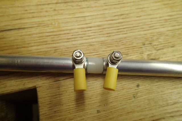
You can then fix that into the insulators. It should look something like this
5 Loop Ends
You might have brought these from Justin. I did with my first beam. Or you have bent them using a tube bender (mine is a brake pipe bender) to EXACTLY the right dimensions
These are the bits you need to adjust at the end to tune the antenna, so make sure they slide in and out. Once you have tuned them you can pop rivet or self tap in place.
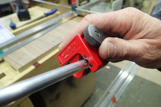
6 Elements
Next bit is easy. Cut the elements to the right lengths and fit them into the insulators. Using a small tube cutter makes a neat job of it.
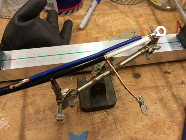
7 Balun
I should have taken more pictures of this but we were getting excited about testing!
Justin has details of something called Pawsey Stub. Don't ask me how it works - i'm only an intermediate!!. We just followed the instructions and bingo it works.
More radio magic.
The idea is that you connect the centre coax feed point onto the loop back to the braid of the coax by 1/4 wave. That needs to be exact and, here you are going to be really impressed, because you need to take into account the velocity factor. Of course. You find that in the data from whoever makes your coax. It is the amount that the coax slows down the speed of the wave - so if you have more than 1 it is not the right figure.
A quick calculation
speed of light/frequency x velocity factor x quarter (WAVE)
or in our case
300/144.3 x .83 x .25 = 43.1cm
Cut a lengthy of wire to that length and join the core at the feed point back to the shield. I stripped off a small bit of the covering and soldered it on and then wrapped the lot in self amalgamating tape.
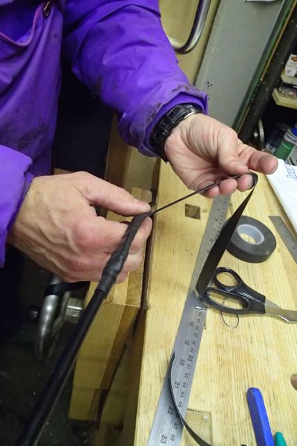
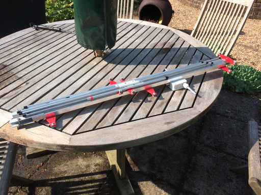
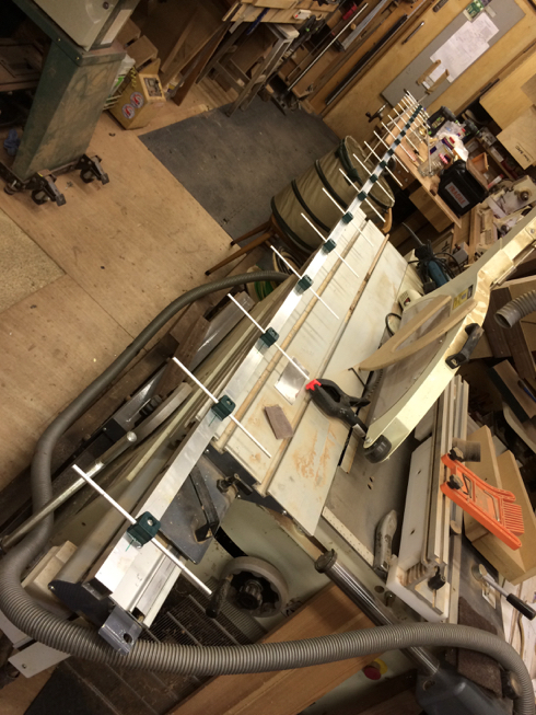
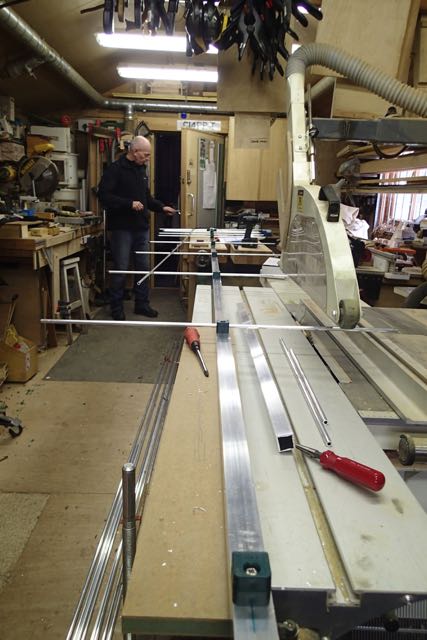
8 Testing Testing......
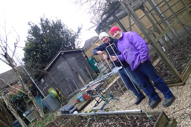
As yet I haven't got a mast to put it on so we did a quick test in the rain on a 10' pole.
You need to adjust the loops that you bent to give the right SWR and we ended up taking 10mm off ours as we made them oversize to start with. It's easier to cut off than to stick back on!
Heres what we got.
And here it is.
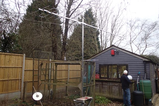
We will update the blog when it has been tested properly. But we are excited that they are going to be so good!
You will find details on his website
We also sells ready built antennas for those not wanting to make them up. Innovantennas
So how did we go about it:
First off you have to decide what you are going to build. We went for a loop fed yagi with a nice 14dBi gain and a 4.5m boom. All the dimensions are on the website as are the suggested tube dimensions. You need to decide on what boom you are going to use and go and order the aluminium.
We went to Aluminium Warehouse via the internet. There is a carriage charge so if you are going to make a few aerials then it pays to buy all you need in one go. You also need to order the insulators from Justin to match the tube size that you have ordered.
When it comes you will need some tools. All pretty basic, saw, rule and the usual soldering stuff we all have. It pays to have a couple of more specialist tools such as a rivnut (or captive nut) installation tool a, pipe cutter and a tube bender. You can get away without these by buying the loop ends from Justin and fixing the insulators with self tappers.
All set? Then off we go.
1 Setting Out
All projects start with reading and understanding the plans and measuring everything out twice before committing to drilling holes.
Mark the actual positions of the elements down the boom and mark the centre lines for the fixings. This one is marked L2 or the 2nd loop element.
2 Riv nut fixing
I like the idea of riv nuts as you can take the elements off for transport and still have a secure fixing. Yes....we are using these for portable operation.
So look at the insulator and line up the bit where the element goes with the line you have marked. The line is NOT where the hole goes. It is where the element goes.
Some insulators have two holes and some one. Make sure you have the right ones. On ours the doubles were for the fed loop and singles for the elements.
You will need to open up the bottom hole in the insulator so it sits flush on the boom over the riv nut
This is what we are aiming for and below is how we get there in more detail.
3 Driven Element Fixing
The driven element is like a dipole and has an insulator between a split tube. The supports will be off each side of the boom so we need to widen it at the driven element.
You will have some of the boom left over which you can chop into two bits and then angle the ends at 45 degrees.
Then pop rivet these on where the 45 degree bit is cut
Then set out the insulators again and drill holes for them
4 Driven Element
You should have also brought Justin's insulator for the driven element to make life easy. Fit it into the two lengths of tube you have cut and drill through for the connecting bolts.
You can then fix that into the insulators. It should look something like this
5 Loop Ends
You might have brought these from Justin. I did with my first beam. Or you have bent them using a tube bender (mine is a brake pipe bender) to EXACTLY the right dimensions
These are the bits you need to adjust at the end to tune the antenna, so make sure they slide in and out. Once you have tuned them you can pop rivet or self tap in place.
6 Elements
Next bit is easy. Cut the elements to the right lengths and fit them into the insulators. Using a small tube cutter makes a neat job of it.
7 Balun
I should have taken more pictures of this but we were getting excited about testing!
Justin has details of something called Pawsey Stub. Don't ask me how it works - i'm only an intermediate!!. We just followed the instructions and bingo it works.
More radio magic.
The idea is that you connect the centre coax feed point onto the loop back to the braid of the coax by 1/4 wave. That needs to be exact and, here you are going to be really impressed, because you need to take into account the velocity factor. Of course. You find that in the data from whoever makes your coax. It is the amount that the coax slows down the speed of the wave - so if you have more than 1 it is not the right figure.
A quick calculation
speed of light/frequency x velocity factor x quarter (WAVE)
or in our case
300/144.3 x .83 x .25 = 43.1cm
Cut a lengthy of wire to that length and join the core at the feed point back to the shield. I stripped off a small bit of the covering and soldered it on and then wrapped the lot in self amalgamating tape.
8 Testing Testing......
As yet I haven't got a mast to put it on so we did a quick test in the rain on a 10' pole.
You need to adjust the loops that you bent to give the right SWR and we ended up taking 10mm off ours as we made them oversize to start with. It's easier to cut off than to stick back on!
Heres what we got.
And here it is.
We will update the blog when it has been tested properly. But we are excited that they are going to be so good!